FUJITSU MHW2120BS User Manual
Page 162
Interface
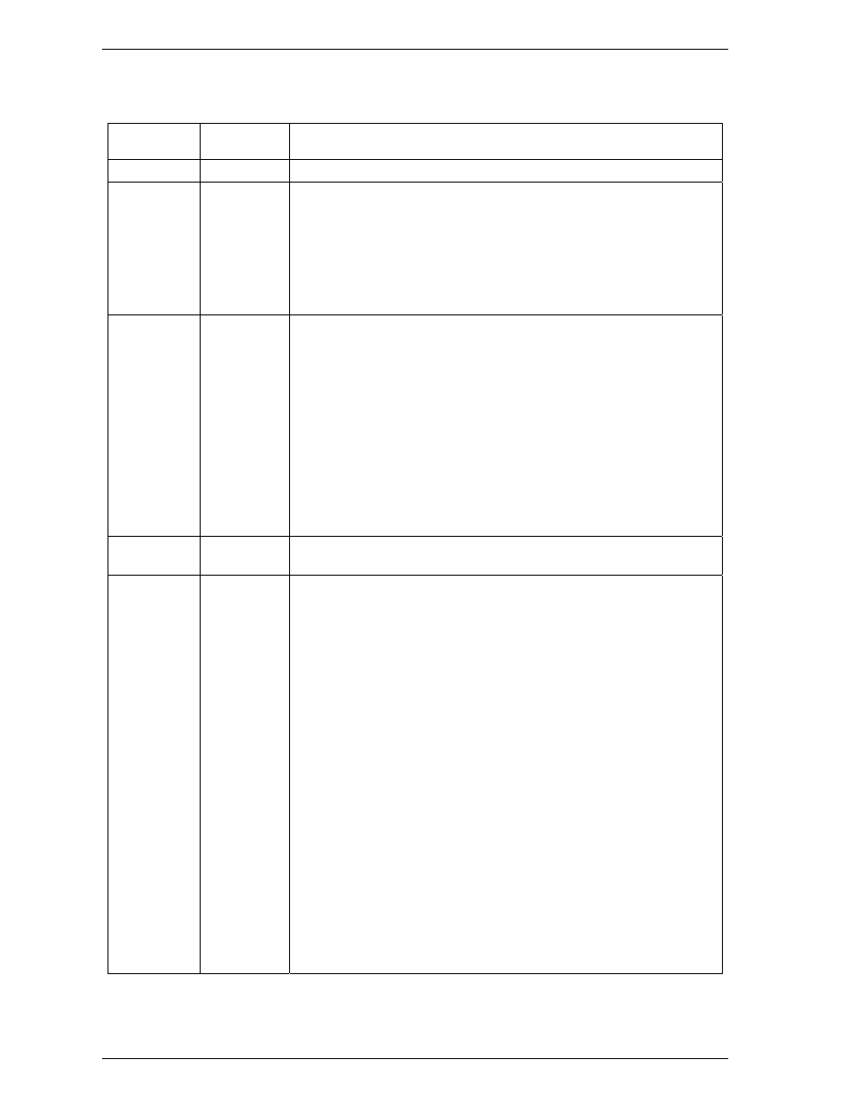
Table 5.33 DEVICE CONFIGURATION IDENTIFY data structure (1/2)
Word Value
Content
0
X'0002'
Data structure revision
1
X'0007'
Multiword DMA modes supported
Reflected in IDENTIFY information "WORD63".
Bits 15-3: Reserved
Bit 2:
1 = Multiword DMA mode 2 and below are supported
Bit 1:
1 = Multiword DMA mode 1 and below are supported
Bit 0:
1 = Multiword DMA mode 0 is supported
2
X'003F'
Ultra DMA modes supported
Reflected in IDENTIFY information "WORD88".
Bits 15-7: Reserved
Bit 6: 1 = Ultra DMA mode 6 and below are supported
Bit 5:
1 = Ultra DMA mode 5 and below are supported
Bit 4:
1 = Ultra DMA mode 4 and below are supported
Bit 3:
1 = Ultra DMA mode 3 and below are supported
Bit 2:
1 = Ultra DMA mode 2 and below are supported
Bit 1:
1 = Ultra DMA mode 1 and below are supported
Bit 0:
1 = Ultra DMA mode 0 is supported
3 to 6
-
Maximum LBA address Reflected in IDENTIFY information
"WORD60-61". (WORD100-103) *
7 X'79CF'
*
Command set/feature set supported
Reflected in IDENTIFY information "WORD82-87".
Bit 15:
Reserved
Bit 14:
1 = Write Read Verify feature supported
Bit 13:
1 = SMART Conveyance self-test supported
Bit 12:
1 = SMART Selective self-test supported
Bit 11: 1 = FUA (Forced Unit Access) supported
Bit 9:
1 = Streaming feature set supported
Bit 10:
Reserved
Bit 8:
1 = 48-bit Addressing feature set supported
Bit 7:
1 = Host Protected Area feature set supported
Bit 6:
1 = Automatic acoustic management supported
Bit 5:
1 = READ/WRITE DMA QUEUED commands supported
Bit 4:
1 = Power-up in Standby feature set supported
Bit 3:
1 = Security feature set supported
Bit 2:
1 = SMART error log supported
Bit 1:
1 = SMART self-test supported
Bit 0:
1 = SMART feature set supported
5-88
C141-E249