Operational analysis, Part 4, Page 89 – Bryant ASPAS1BBA015 User Manual
Page 89
Page 89
SECTION 4.2
OPERATIONAL ANALYSIS
DC CONTROL
PART 4
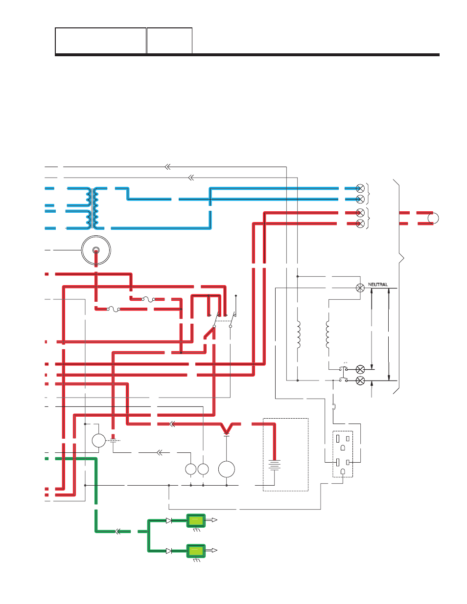
• The battery charge relay (BCR) connected to Wire
14 will be de-energized. This will cause transformer
(TX) voltage to power the battery charger again.
• Circuit board action will connect the engine's
ignition shutdown module (ISM) to ground, via Wire
18, circuit board Pin 13, and Wire 0. Ignition will be
terminated.
• Without fuel flow and without ignition, the engine
will shut down.
F1
SM
C1-1
15
0
0
18
C1-5
56
18
17
15
17
15A
SCR
0
0
0
15
16
239
15
14
0
194
23
13
18
D
IM2
IM1
SP2
SP1
23
16
0
13
SC
0
SW1
15
15A
239
194
FS
0
14
C2-1
WINDING
(STATOR)
POWER
22
44
11
CB1
33
56VA
1VA
13
225
225A
224A
224
TX
17
N1
N2
11
22
C2-5
N2
N1
C2-6
11
194
23
194
23
N1
N2
CUSTOMER
SUPPLIED
BATTERY
12V
BLACK
RED
SC
240V
120V
120V
CUSTOMER
CONNECTIONS
COIL
12Vdc
UTILITY
INPUT
240VAC
RELAY
TRANSFER
TR
12VDC ACCESSORY SOCKET
+
-
14
0
0
15
17
22
N
11
23
194
22
D
GFCI
OUTLET
EXTERNAL
G
G
G
L
N
L
11
G
G
N
N
CB3
N
0
0
15
15
15
13
15
15B
15B
F2
0
0
239
Figure 7. Circuit Condition - Retransfer to “Utility”
and Engine Shutdown