Introduction, Utility source voltage available, Operational analysis part 4 – Bryant ASPAS1BBA015 User Manual
Page 76: Page 76
SECTION 4.2
OPERATIONAL ANALYSIS
PART 4
DC CONTROL
INTRODUCTION
This "Operational Analysis" is intended to familiarize
the service technician with the operation of the DC
control system on prepackaged units with air-cooled
engine. A thorough understanding of how the system
works is essential to sound and logical
troubleshooting. The DC control system illustrations
on the following pages include a "V-Type"
prepackaged transfer switch.
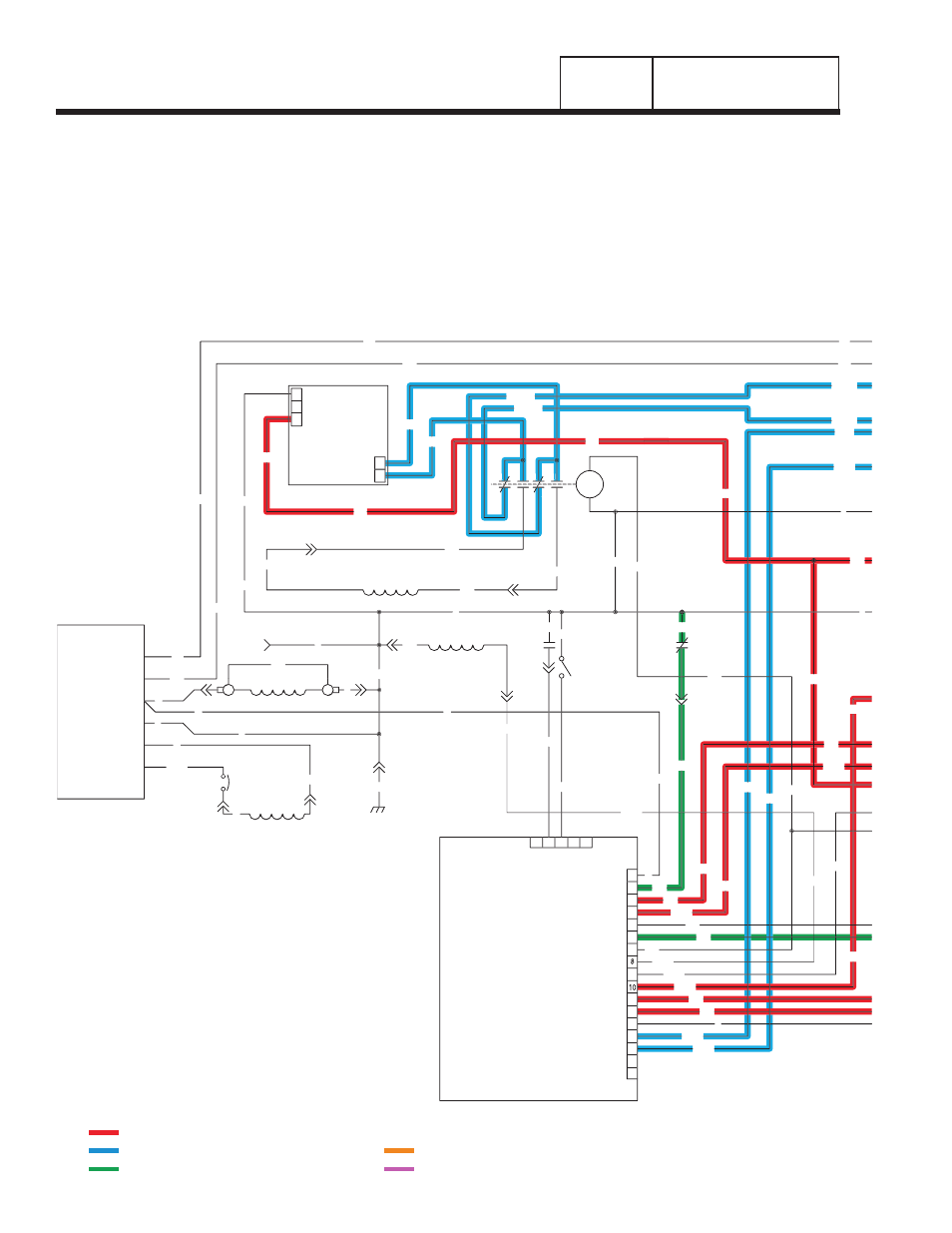
UTILITY SOURCE VOLTAGE AVAILABLE
See Figure 1, above. The circuit condition with the
Auto-Off-Manual switch set to AUTO and with "Utility"
source power available can be briefly described as
follows:
• "Utility" source voltage is available to transfer switch
terminal lugs N1/N2. With the transfer switch main
contacts at their "Utility" side, this source voltage is
available to terminal lugs T1/T2 and to the "Load"
circuits.
CHARGER
BATTERY
0
162
22
VOLTAGE
REGULATOR
ELECTRONIC
6
4
0
11
(STATOR)
DPE WINDING
C2-8
2
C2-7
C2-11
C2-10
CB2
4
0
22
6
BA
FIELD
0
13
11
0
77
C2-1
3
1
2
C1-3
4
14
11
16
17
12
13
15
14
C2-3
PRINTED CIRCUIT
0
C1-6
C2-9
0
0
55
C2-4
4
0
WINDING
ENGINE RUN
(STATOR)
66
CONTROL
BOARD
3
2
1
J2
3
7
9
4
6
5
J1
5
4
1
2
66A
66A
85
351
HTO
C1-4
C2-2
0
0
SW2
17
225
15
224
0
66A
14
194
23
194
56
15A
66A
239
18
86
23
224
4
86
0
LOP
14
225
239
15A
23
194
13
225B
BATTERY CHARGE
WINDING
13
1
2
77
224B
11
22
1
6
66
3
3
4
225A
224A
9
9
7
7
7
7
9
9
BCR
0
14
13
13
13
0
0
224
225A
225
224A
22
11
0
0
15A
TX - TRANSFORMER, 16 Vac 56 VA & 16 Vac 1 VA (DUAL SEC.)
DIAGRAM KEY
BA - BRUSH ASSEMBLY
SCR - STARTER CONTACTOR RELAY
SC - STARTER CONTACTOR
HTO - HIGH OIL TEMPERATURE SWITCH
FS - FUEL SOLENOID
CB1 - CIRCUIT BREAKER, MAIN OUTPUT
LOP - LOW OIL PRESSURE SWITCH
IM2 - IGNITION MODULE, CYLINDER #2
IM1 - IGNITION MODULE, CYLINDER #1
SW1 - AUTO / OFF / MANUAL SWITCH
SM - STARTER MOTOR
SW2 - SET EXERCISE SWITCH
SP1, SP2 - SPARK PLUGS
CB2 - CIRCUIT BREAKER, ALT. EXCITATION
BCR - BATTERY CHARGE RELAY
F2 - FUSE 7.5 AMP
D - DIODE
F1 - FUSE 15 AMP
CB3 - CIRCUIT BREAKER, EXTERNAL OUTLET, PUSH/PULL
= 12 VDC ALWAYS PRESENT
= AC VOLTAGE
= GROUND FOR CONTROL PURPOSES
= 12 VDC DURING CRANKING ONLY
= 12 VDC DURING ENGINE RUN CONDITION
Page 76