Operational analysis, Part 4, Figure 3. circuit condition - engine cranking – Bryant ASPAS1BBA015 User Manual
Page 81: Page 81
Page 81
SECTION 4.2
OPERATIONAL ANALYSIS
DC CONTROL
PART 4
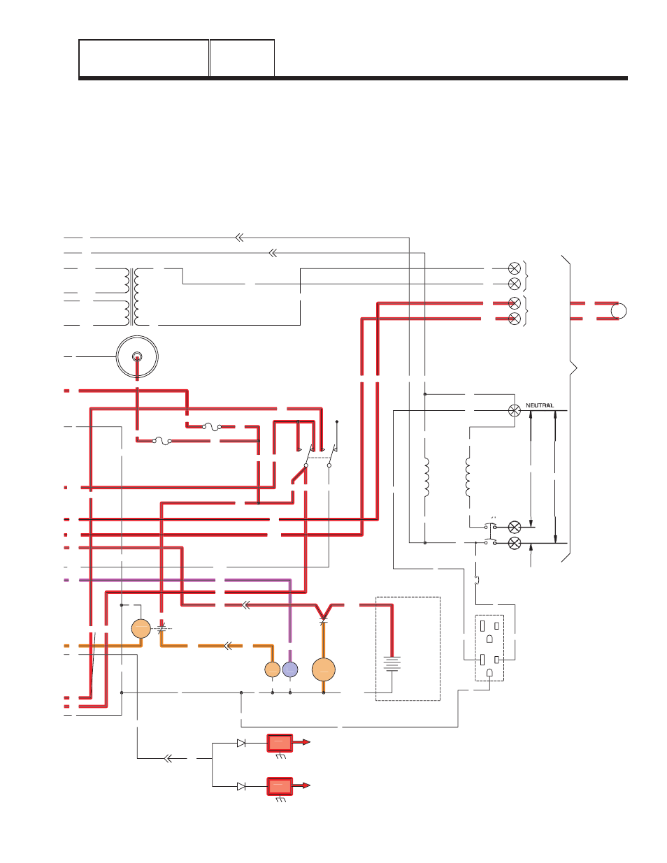
• When the circuit board's run relay (K2) energizes,
12 volts DC is delivered to a fuel solenoid (FS), via
Wire 14. The fuel solenoid (FS) energizes open and
fuel is available to the engine. Wire 14 energizes
the battery charge relay (BCR), which will allow the
BCR to power the battery charger.
• As the engine cranks, magnets on the engine
flywheel induce a high voltage into the engine
ignition modules (IM1/IM2). A spark is produced
that jumps the spark plug (SP1/SP2) gap.
• During cranking, Wire 4 supplies 2-3 VDC (8-9 VDC
isolated) to the rotor for field flash.
• With ignition and fuel flow available the engine can
start.
F1
SM
C1-1
15
0
0
18
C1-5
56
18
17
15
17
15A
SCR
0
0
0
15
16
239
15
14
0
194
23
13
18
D
IM2
IM1
SP2
SP1
23
16
0
13
SC
0
SW1
15
15A
239
194
FS
0
14
C2-1
WINDING
(STATOR)
POWER
22
44
11
CB1
33
56VA
1VA
13
225
225A
224A
224
TX
17
N1
N2
11
22
C2-5
N2
N1
C2-6
11
194
23
194
23
N1
N2
CUSTOMER
SUPPLIED
BATTERY
12V
BLACK
RED
SC
240V
120V
120V
CUSTOMER
CONNECTIONS
COIL
12Vdc
UTILITY
INPUT
240VAC
RELAY
TRANSFER
TR
12VDC ACCESSORY SOCKET
+
-
14
0
0
15
17
22
N
11
23
194
22
D
GFCI
OUTLET
EXTERNAL
G
G
G
L
N
L
11
G
G
N
N
CB3
N
0
0
15
15
15
13
15
15B
15B
F2
0
0
239
Figure 3. Circuit Condition - Engine Cranking