Bryant ASPAS1BBA015 User Manual
Page 127
Page 127
SECTION 6.1
MAJOR DISASSEMBLY
DISASSEMBLY
PART 6
Remove the two bolts attaching the muffler side cover to
the back enclosure panel. They are located in the center
of the back panel. Remove the alternator panel and
muffler side cover as an assembly.
Figure 3
13.Remove Muffler: Using a 13mm socket, remove the
four muffler hold down bolts. Remove the four exhaust
manifold nuts. Remove the muffler and muffler base
panel.
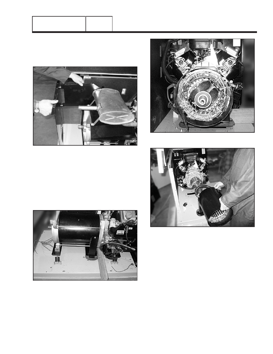
14.Stator Removal: Using a 13mm socket, remove the
two nuts from the alternator mounting bracket/rubber
mounts. Lift the back end of the alternator up and place
a 2"x 4" piece of wood under the engine adapter.
Figure 4. Engine Adapter Supported by
2”x4” Piece of Wood
Using a 1/4" socket, remove Wire 0 and Wire 4 from the
brush assembly. Remove the two brush assembly hold
down bolts. Remove the brushes.
Using a 13mm socket, remove the four stator hold down
bolts. Using a small rubber mallet remove the rear
bearing carrier. Remove the stator.
Figure 5. Rear Bearing Carrier Removed
Figure 6. Removing the Stator
15.Rotor Removal: Cut 2.5 inches from the rotor bolt. Slot
the end of the bolt to suit a flat blade screwdriver. Slide
the rotor bolt back through the rotor and use a
screwdriver to screw it into the crankshaft. Use a 3"
M12x1.75 bolt to screw into rotor. Apply torque to the 3"
M12x1.75 bolt until taper breaks. If necessary, when
torque is applied to 3" M12x1.75 bolt, use a rubber
mallet on the end of the rotor shaft to break taper.