Operational analysis, Part 4, Page 77 – Bryant ASPAS1BBA015 User Manual
Page 77
Page 77
SECTION 4.2
OPERATIONAL ANALYSIS
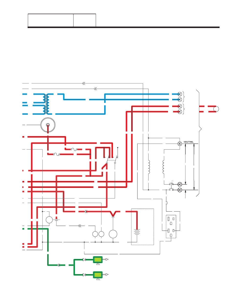
DC CONTROL
PART 4
• "Utility" voltage is delivered to the primary winding
of a sensing transformer (TX), via transfer switch
wires N1/N2, fuses F1/F2, connected wiring, and
Control Panel "Utility 1/Utility 2" terminals. A
resultant voltage (about 16 volts AC) is induced into
the transformer secondary windings and then
delivered to the circuit board via Wires 224/225.
The circuit board uses this reduced "Utility" voltage
as sensing voltage. Wires 224A/225A supply 16
VAC to the battery charger.
• Battery output is delivered to the circuit board with
the Auto-Off-Manual switch (SW1) set to AUTO, as
shown.
F1
SM
C1-1
15
0
0
18
C1-5
56
18
17
15
17
15A
SCR
0
0
0
15
16
239
15
14
0
194
23
13
18
D
IM2
IM1
SP2
SP1
23
16
0
13
SC
0
SW1
15
15A
239
194
FS
0
14
C2-1
WINDING
(STATOR)
POWER
22
44
11
CB1
33
56VA
1VA
13
225
225A
224A
224
TX
17
N1
N2
11
22
C2-5
N2
N1
C2-6
11
194
23
194
23
N1
N2
CUSTOMER
SUPPLIED
BATTERY
12V
BLACK
RED
SC
240V
120V
120V
CUSTOMER
CONNECTIONS
COIL
12Vdc
UTILITY
INPUT
240VAC
RELAY
TRANSFER
TR
12VDC ACCESSORY SOCKET
+
-
14
0
0
15
17
22
N
11
23
194
22
D
GFCI
OUTLET
EXTERNAL
G
G
G
L
N
L
11
G
G
N
N
CB3
N
0
0
15
15
15
13
15
15B
15B
F2
0
0
239
Figure 1. Circuit Condition - Utility Source Voltage
Available