Operational analysis, Part 4, Page 85 – Bryant ASPAS1BBA015 User Manual
Page 85
SECTION 4.2
OPERATIONAL ANALYSIS
DC CONTROL
PART 4
Page 85
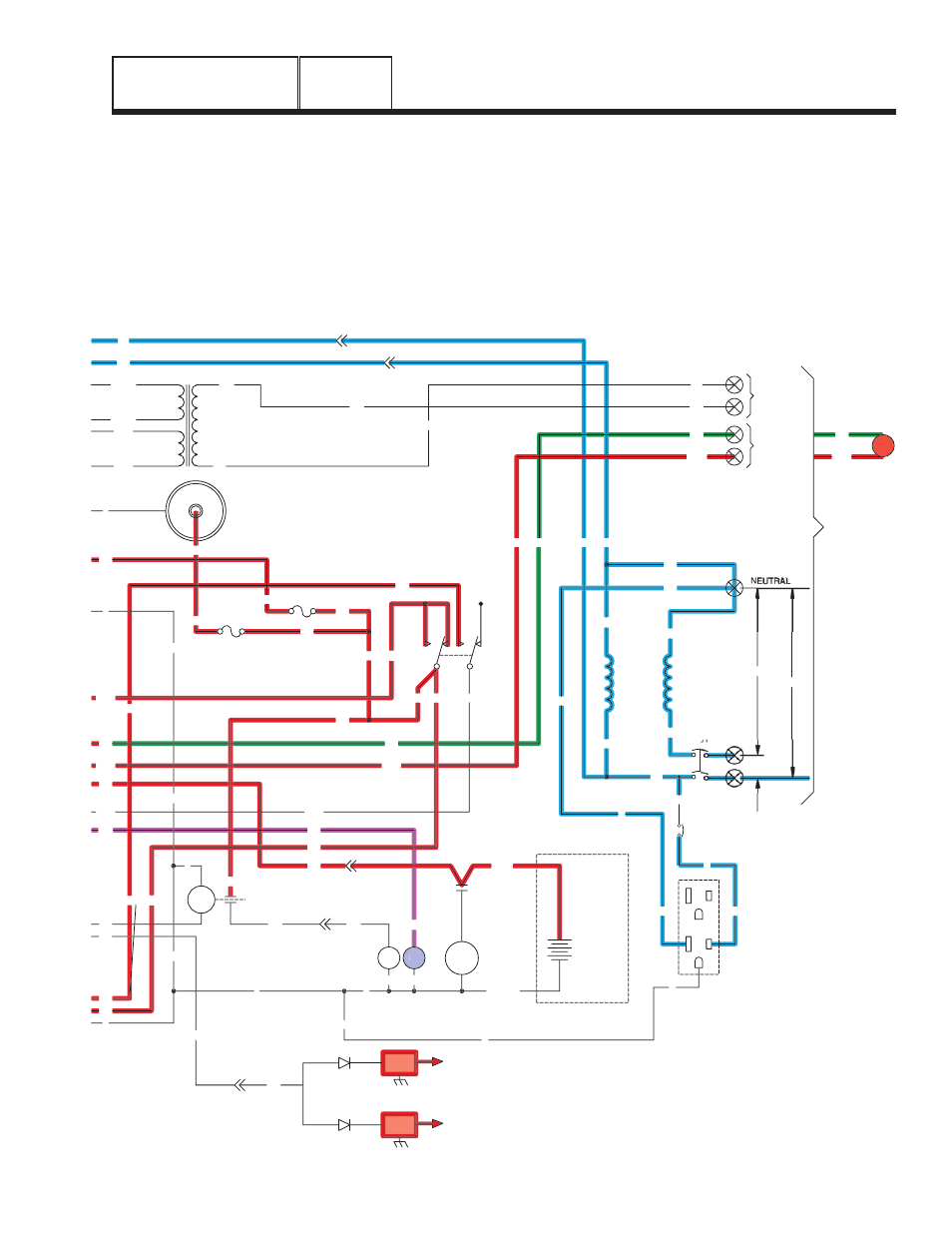
XB1, Wire B, and a bridge rectifier. The standby
closing coil energizes and the main current carrying
contacts of the transfer switch are actuated to their
'Standby" source side.
• As the main contacts move to their "Standby"
source side, a mechanical interlock actuates limit
switch XB1 to its open position and limit switch XA1
to its "Utility" side position. When XB1 opens,
standby closing coil C2 3 de-energizes.
• "Standby" power is delivered to the "Load"
terminals (T1/T2) of the transfer switch.
F1
SM
C1-1
15
0
0
18
C1-5
56
18
17
15
17
15A
SCR
0
0
0
15
16
239
15
14
0
194
23
13
18
D
IM2
IM1
SP2
SP1
23
16
0
13
SC
0
SW1
15
15A
239
194
FS
0
14
C2-1
WINDING
(STATOR)
POWER
22
44
11
CB1
33
56VA
1VA
13
225
225A
224A
224
TX
17
N1
N2
11
22
C2-5
N2
N1
C2-6
11
194
23
194
23
N1
N2
CUSTOMER
SUPPLIED
BATTERY
12V
BLACK
RED
SC
240V
120V
120V
CUSTOMER
CONNECTIONS
COIL
12Vdc
UTILITY
INPUT
240VAC
RELAY
TRANSFER
TR
12VDC ACCESSORY SOCKET
+
-
14
0
0
15
17
22
N
11
23
194
22
D
GFCI
OUTLET
EXTERNAL
G
G
G
L
N
L
11
G
G
N
N
CB3
N
0
0
15
15
15
13
15
15B
15B
F2
0
0
239
Figure 5. Circuit Condition - Initial Transfer to
Standby