Initial transfer to the "standby" source, Operational analysis part 4, Page 84 – Bryant ASPAS1BBA015 User Manual
Page 84
Page 84
SECTION 4.2
OPERATIONAL ANALYSIS
PART 4
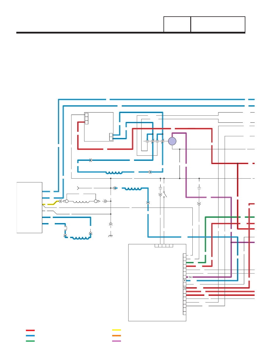
DC CONTROL
INITIAL TRANSFER TO THE "STANDBY"
SOURCE
The generator is running, the circuit board's "engine
warm-up timer" is timing, and generator AC output is
available to transfer switch terminal lugs E1 and E2
and to the open contacts on the transfer relay. Initial
transfer to the "Standby" power supply may be briefly
described as follows:
• The circuit board delivers a 12 volts DC output to
the transfer relay (TR) actuating coil, via Wire 194,
and terminal A of the transfer relay (TR) in the
transfer switch. This 12 volts DC circuit is
completed back to the board, via transfer relay
terminal B, and Wire 23. However, circuit board
action holds the Wire 23 circuit open to ground and
the transfer relay (TR) is de-energized.
• When the circuit board's "engine warm-up timer"
times out, circuit board action completes the Wire
23 circuit to ground. The transfer relay then
energizes and its normally open contacts close.
• "Standby" power is now delivered to the standby
closing coil (C2), via Wires E1 /E2, the normally
open transfer relay contacts, Wire 205, limit switch
CHARGER
BATTERY
0
162
22
VOLTAGE
REGULATOR
ELECTRONIC
6
4
0
11
(STATOR)
DPE WINDING
C2-8
2
C2-7
C2-11
C2-10
CB2
4
0
22
6
BA
FIELD
0
13
11
0
77
C2-1
3
1
2
C1-3
4
11
16
17
12
13
15
14
C2-3
PRINTED CIRCUIT
0
C1-6
C2-9
0
0
55
C2-4
4
0
WINDING
ENGINE RUN
(STATOR)
66
CONTROL
BOARD
3
2
1
J2
3
7
9
4
6
5
J1
5
4
1
2
66A
66A
85
351
HTO
C1-4
C2-2
0
0
SW2
17
225
15
224
0
66A
14
194
23
194
56
15A
66A
239
18
86
23
224
4
86
0
LOP
14
225
239
15A
23
194
13
225B
BATTERY CHARGE
WINDING
13
1
2
77
224B
11
22
1
6
66
3
4
225A
224A
9
9
7
7
7
7
9
9
BCR
0
14
13
13
13
0
0
224
225A
225
224A
22
11
0
0
15A
TX - TRANSFORMER, 16 Vac 56 VA & 16 Vac 1 VA (DUAL SEC.)
DIAGRAM KEY
BA - BRUSH ASSEMBLY
SCR - STARTER CONTACTOR RELAY
SC - STARTER CONTACTOR
HTO - HIGH OIL TEMPERATURE SWITCH
FS - FUEL SOLENOID
CB1 - CIRCUIT BREAKER, MAIN OUTPUT
LOP - LOW OIL PRESSURE SWITCH
IM2 - IGNITION MODULE, CYLINDER #2
IM1 - IGNITION MODULE, CYLINDER #1
SW1 - AUTO / OFF / MANUAL SWITCH
SM - STARTER MOTOR
SW2 - SET EXERCISE SWITCH
SP1, SP2 - SPARK PLUGS
CB2 - CIRCUIT BREAKER, ALT. EXCITATION
BCR - BATTERY CHARGE RELAY
F2 - FUSE 7.5 AMP
D - DIODE
F1 - FUSE 15 AMP
CB3 - CIRCUIT BREAKER, EXTERNAL OUTLET, PUSH/PULL
= 12 VDC ALWAYS PRESENT
= AC VOLTAGE
= GROUND FOR CONTROL PURPOSES
= 12 VDC DURING CRANKING ONLY
= DC FIELD CONTROL VOLTAGE
= 12 VDC DURING ENGINE RUN CONDITION