Fuse holder – Bryant ASPAS1BBA015 User Manual
Page 49
Page 49
SECTION 3.1
DESCRIPTION & COMPONENTS
delivered to a step-down transformer in the control
module assembly and the resultant reduced voltage is
then delivered to the circuit board. Utility 1 and 2
power is used by the circuit board as follows:
• If utility source voltage should drop below a preset
level, circuit board action will initiate automatic
cranking and startup, followed by automatic transfer
to the standby source.
• Utility source voltage is used to operate a battery
trickle charge circuit which helps to maintain battery
state of charge during non-operating periods.
TERMINALS 23 AND 194:
These terminals connect the transfer relay to the
generator circuit board. See "Transfer Relay" in
Section 3.1.
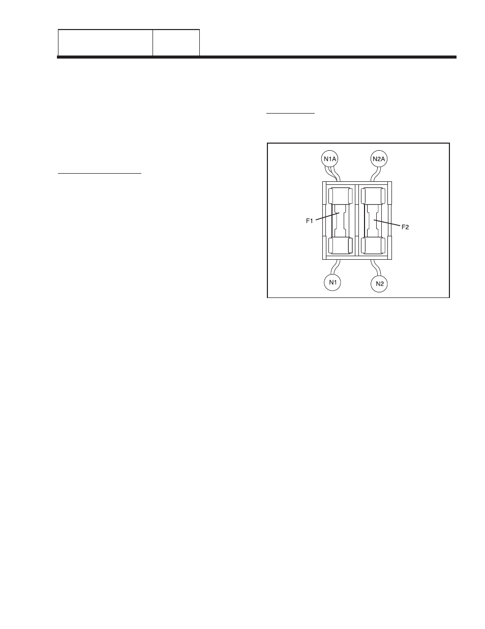
FUSE HOLDER
The fuse holder holds two (2) fuses, designated as
fuses F1 and F2. Each fuse is rated 5 amperes.
FUSES F1, F2:
These two fuses protect the terminal board UTILITY 1
and 2 circuit against overload.
Figure 7. The Fuse Holder
“V-TYPE” PREPACKAGED
TRANSFER SWITCHES
PART 3