Bryant ASPAS1BBA015 User Manual
Page 109
SECTION 4.4
DIAGNOSTIC TESTS
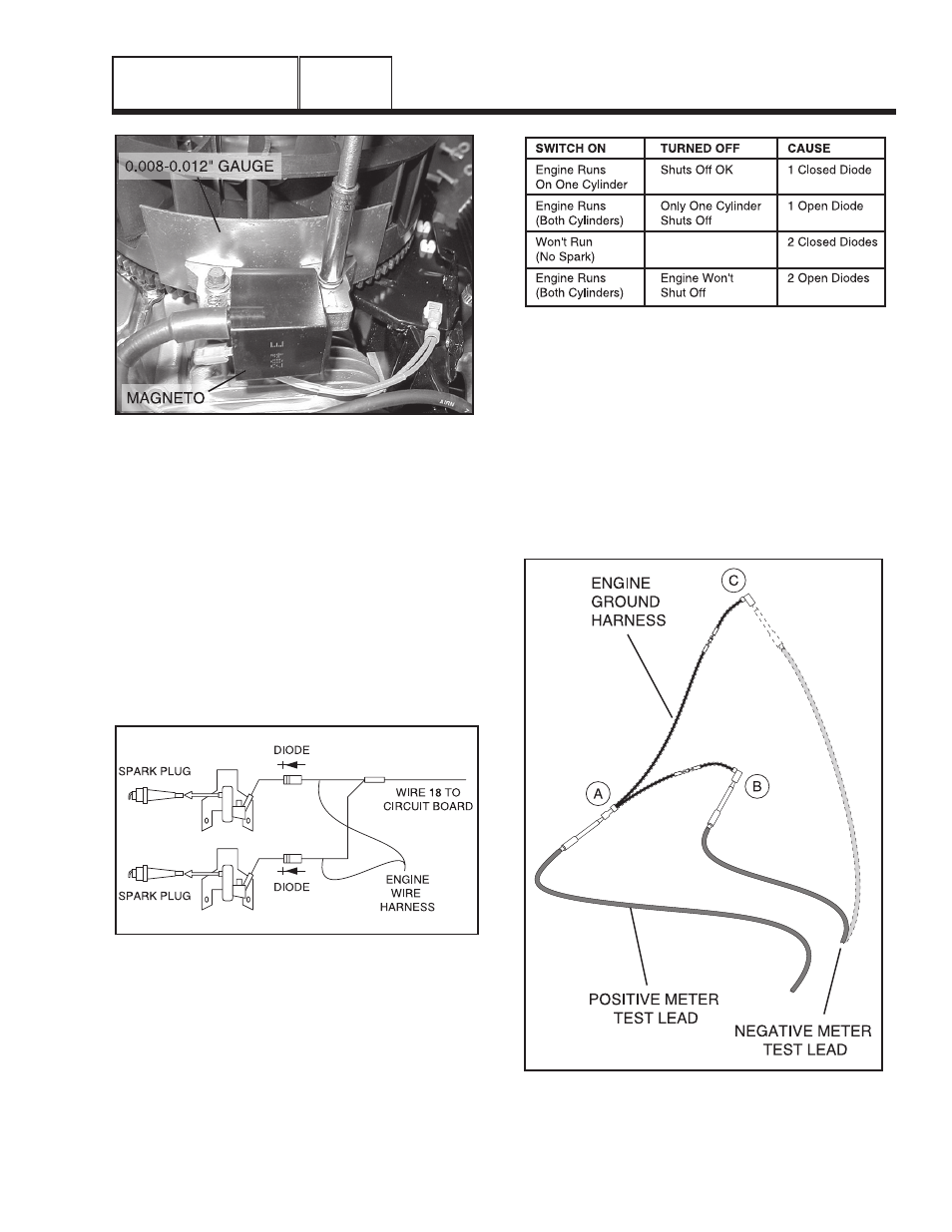
Figure 23. Setting Ignition Magneto (Armature)
Air Gap
7. Repeat Test 55 and check for spark across the spark
tester gap.
8. If air gap was not out of adjustment, test ground wires.
9. Set the VOM to the diode test position. The meter will
display forward voltage drop across the diode. If the
voltage drop is less than 0.7 volts, the meter will “Beep”
once as well as display the voltage drop. A continuous
tone indicates CONTINUITY (shor ted diode). An
incomplete circuit (open diode) will be displayed as “OL.”
10.Disconnect the engine wire harness from the ignition
magnetos and stud connector (Figure 24).
Figure 24. Engine Ground Harness
Figure 25. Diode Failure Diagnosis
11.Connect the positive (+) test lead to Connector ”A” (as
shown in Figure 26). Connect the negative (-) test lead
to Connector “B.”
a. If meter “Beeps” once and displays voltage
drop, then the diode is good.
b. If the meter makes a continuous tone, the diode
is bad (shorted) and the harness must be
replaced.
c. If the meter displays “OL,” the diode is defective
(open) and the harness must be replaced.
Figure 26. Engine Ground Harness Test Points
DC CONTROL
PART 4
Page 109