Test 24- check manual transfer switch operation – Bryant ASPAS1BBA015 User Manual
Page 63
Page 63
SECTION 3.4
DIAGNOSTIC TESTS
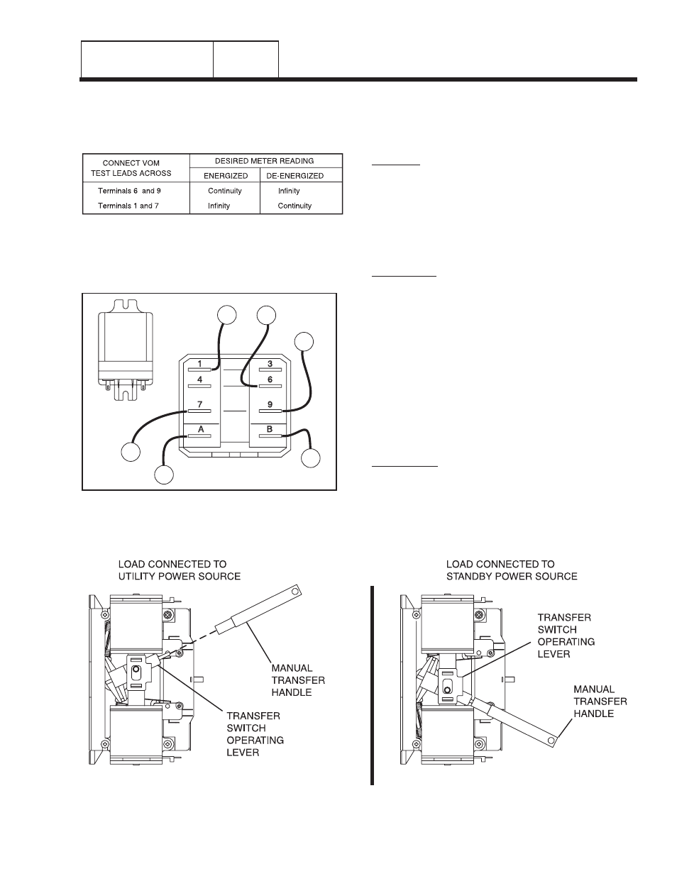
3. Connect the VOM test leads across Relay Terminals 6
and 9 with the relay de-energized. The VOM should
read infinity.
4. Using jumper wires, connect the positive (+) post of a 12
volt battery to relay Terminal “A” and the negative (-)
battery post to Relay Terminal "B". The relay should
energize and the VOM should read CONTINUITY.
Figure 2. Transfer Relay Test Points
5. Now, connect the VOM test leads across Relay
Terminals 1 and 7.
a. Energize the relay and the meter should
indicate infinity.
b. De-energize the relay and the VOM should read
CONTINUITY.
RESULTS:
1. Replace transfer relay if it is defective.
2. If transfer relay checks good go to Test 26.
TEST 24- CHECK MANUAL TRANSFER
SWITCH OPERATION
DISCUSSION:
In automatic operating mode, when utility source
voltage drops below a preset level, the engine should
crank and start. On engine startup, an "engine warm-
up timer" on the generator circuit board should start
timing. When that timer has timed out (about 15
seconds), the transfer relay should energize to deliver
utility source power to the standby closing coil
terminals. If normal utility source voltage is available
to the standby closing coil terminals, but transfer to
Standby does not occur, the cause of the failure may
be (a) a failed standby closing coil and/or bridge
rectifier, or (b) a seized or sticking actuating coil or
load contact. This test will help you evaluate whether
any sticking or binding is present in the transfer
mechanism.
PROCEDURE:
1. With the generator shut down, set the generator Auto-
Off-Manual switch to OFF.
2. Set the generator main circuit breaker to OFF or "Open".
3. Turn off the utility power supply to the transfer switch,
194
N1A
126
205
E1
23
“V-TYPE” PREPACKAGED
TRANSFER SWITCHES
PART 3
Figure 3. Manual Transfer Switch Operation