Bryant ASPAS1BBA015 User Manual
Page 122
Page 122
SECTION 5.1
SYSTEM FUNCTIONAL TESTS
INTRODUCTION
Following home standby electric system installation
and periodically thereafter, the system should be
tested Functional tests of the system include the
following:
• Manual transfer switch operation.
• System voltage tests.
• Generator Tests Under Load.
• Testing automatic operation.
Before proceeding with functional tests, read
instructions and information on tags or decals affixed
to the generator and transfer switch. Perform all tests
in the exact order given in this section.
MANUAL TRANSFER SWITCH OPERATION
"V-TYPE" TRANSFER SWITCHES:
1. On the generator panel, set the Auto-Off-Manual switch
to OFF.
2. Turn OFF the "Utility" power supply to the transfer switch
using whatever means provided (such as a "Utility" main
line circuit breaker).
3. Set the generator main line circuit breaker to OFF or
"Open".
DANGER: BE SURE TO TURN OFF ALL
POWER VOLTAGE SUPPLIES TO THE
TRANSFER SWITCH BEFORE ATTEMPTING
MANUAL OPERATION. FAILURE TO TURN
OFF POWER VOLTAGE SUPPLIES TO THE
TRANSFER SWITCH MAY RESULT IN
DANGEROUS AND POSSIBLY LETHAL
ELECTRICAL SHOCK.
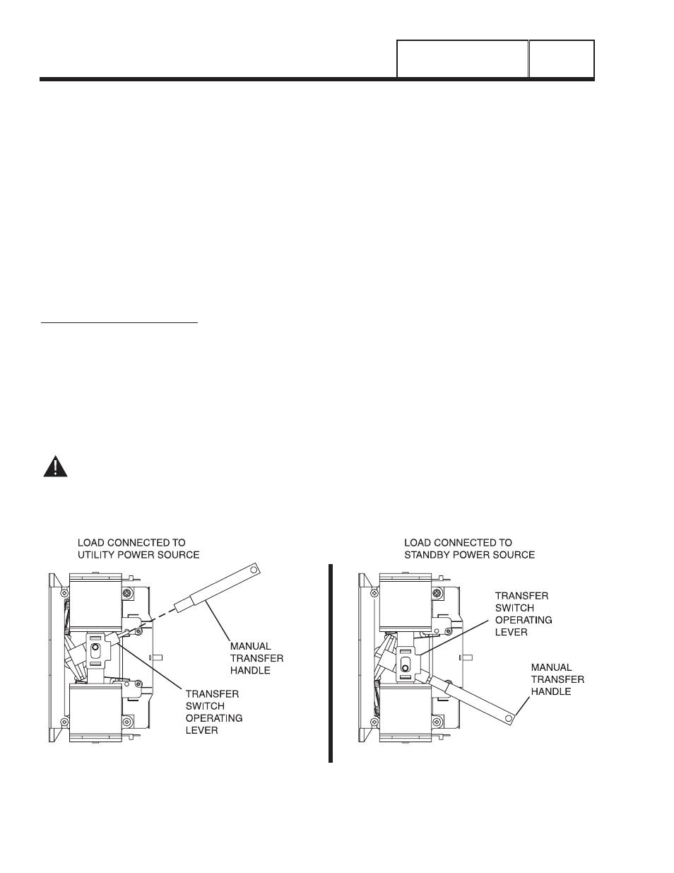
4. Remove the manual transfer handle from the enclosure.
5. Place open end of the manual transfer handle over
transfer switch operating lever.
6. To connect "Load" terminal lugs to the "Standby" power
source, move, the handle upward.
7. To connect "Load" terminals to the Utility" power source,
move the handle downward.
8. Actuate the switch to "Utility" and to MANUAL several
times. Make sure no evidence of binding or interference
is felt.
9. When satisfied that manual transfer switch operation is
correct, actuate the main contacts to their "Utility"
position ("Load" connected to the "Utility" power supply).
ELECTRICAL CHECKS
Complete electrical checks as follows:
1. Set the generator main circuit breaker to its OFF (or
open) position.
2. Set the generator Auto-Off-Manual switch to the “OFF “
position.
3. Turn off all loads connected to the transfer switch
terminals T1 and T2.
4. Turn on the utility power supply to the transfer switch
OPERATIONAL TESTS
AND ADJUSTMENTS
PART 5
Figure 1. Manual Operation “V-Type” Switch