Utility voltage restored / re- transfer to utility, Operational analysis part 4, Page 86 – Bryant ASPAS1BBA015 User Manual
Page 86
Page 86
SECTION 4.2
OPERATIONAL ANALYSIS
PART 4
DC CONTROL
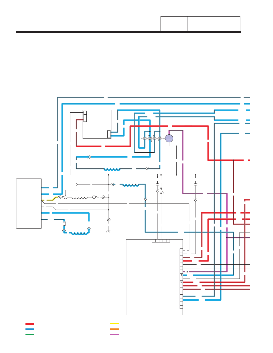
UTILITY VOLTAGE RESTORED / RE-
TRANSFER TO UTILITY
The "Load" is powered by the "Standby" power
supply. The circuit board continues to seek an
acceptable "Utility" source voltage. On restoration of
"Utility" source voltage, the following events will
occur:
• On restoration of utility source voltage above 80
percent of the nominal rated voltage, a "retransfer
time delay" on the circuit board starts timing. The
timer will run for about fifteen (15) seconds.
• At the end of fifteen (15) seconds, the "retransfer
time delay" will stop timing and circuit board action
will open the Wire 23 circuit to ground. The transfer
relay (TR) will then de-energize.
• When the transfer relay (TR) de-energizes, its
normally-closed contacts close. "Utility" source
voltage is then delivered to the utility closing coil
(C1), via Wires N1A/N2A, the closed TR contacts,
Wire 126, limit switch XA1, and a bridge rectifier.
• The utility closing coil (C1) energizes and moves
the main current carrying contacts to their "Neutral"
position. The main contacts move to an over center
CHARGER
BATTERY
0
162
22
VOLTAGE
REGULATOR
ELECTRONIC
6
4
0
11
(STATOR)
DPE WINDING
C2-8
2
C2-7
C2-11
C2-10
CB2
4
0
22
6
BA
FIELD
0
13
11
0
77
C2-1
3
1
2
C1-3
4
11
16
17
12
13
15
14
C2-3
PRINTED CIRCUIT
0
C1-6
C2-9
0
0
55
C2-4
4
0
WINDING
ENGINE RUN
(STATOR)
66
CONTROL
BOARD
3
2
1
J2
3
7
9
4
6
5
J1
5
4
1
2
66A
66A
85
351
HTO
C1-4
C2-2
0
0
SW2
17
225
15
224
0
66A
14
194
23
194
56
15A
66A
239
18
86
23
224
4
86
0
LOP
14
225
239
15A
23
194
13
225B
BATTERY CHARGE
WINDING
13
1
2
77
224B
11
22
1
66
3
4
225A
224A
7
7
9
9
BCR
0
14
13
13
13
0
0
224
225A
225
224A
22
11
0
0
15A
TX - TRANSFORMER, 16 Vac 56 VA & 16 Vac 1 VA (DUAL SEC.)
DIAGRAM KEY
BA - BRUSH ASSEMBLY
SCR - STARTER CONTACTOR RELAY
SC - STARTER CONTACTOR
HTO - HIGH OIL TEMPERATURE SWITCH
FS - FUEL SOLENOID
CB1 - CIRCUIT BREAKER, MAIN OUTPUT
LOP - LOW OIL PRESSURE SWITCH
IM2 - IGNITION MODULE, CYLINDER #2
IM1 - IGNITION MODULE, CYLINDER #1
SW1 - AUTO / OFF / MANUAL SWITCH
SM - STARTER MOTOR
SW2 - SET EXERCISE SWITCH
SP1, SP2 - SPARK PLUGS
CB2 - CIRCUIT BREAKER, ALT. EXCITATION
BCR - BATTERY CHARGE RELAY
F2 - FUSE 7.5 AMP
D - DIODE
F1 - FUSE 15 AMP
CB3 - CIRCUIT BREAKER, EXTERNAL OUTLET, PUSH/PULL
= 12 VDC ALWAYS PRESENT
= AC VOLTAGE
= GROUND FOR CONTROL PURPOSES
= 12 VDC DURING CRANKING ONLY
= DC FIELD CONTROL VOLTAGE
= 12 VDC DURING ENGINE RUN CONDITION