Bryant ASPAS1BBA015 User Manual
Page 42
Page 42
SECTION 2.4
DIAGNOSTIC TESTS
PART 2
AC GENERATORS
RESULTS:
1. Repair, replace or reconnect wires as necessary.
2. Replace any damaged slip rings or brush holder.
3. Clean and polish slip rings as required.
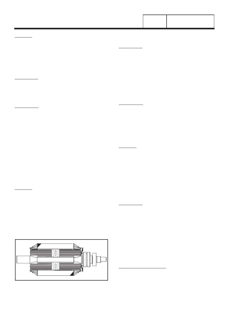
TEST 10 - TEST ROTOR ASSEMBLY
DISCUSSION:
A rotor having completely open windings will cause
loss of excitation current flow and, as a result,
generator AC output voltage will drop to "residual"
voltage. A "shorted" rotor winding can result in a low
voltage condition.
PROCEDURE:
1. Disconnect the brush wires or remove the brush holder,
to prevent interaction.
2. Set a VOM to its "R x 1" scale and zero the meter.
3. Connect the positive (+) VOM test lead to the positive
(+) rotor slip ring (nearest the rotor bearing); and the
common (-) test lead to the negative (-) slip ring. The
meter should read approximately 10-20 ohms. Compare
to “Specifications,” inside front cover.
4. Now, set the VOM to a high resistance scale (such as "R
x 10,000" or "R x 1K"). Again, zero the meter.
5. Connect the positive (+) VOM test lead to the positive
(+) slip ring and the common (-) test lead to a clean
frame ground. The meter should indicate infinity.
RESULTS:
1. Replace rotor assembly if it is open or shorted.
2. If rotor tests good, perform “Insulation Resistance Test”
in Section 1.4.
NOTE: Be sure to read Section 1.4, "Testing,
Cleaning and Drying", carefully. If the rotor tests
good, try performing an insulation resistance test.
Clean and dry the rotor if it fails that test. Then,
repeat the test. If the rotor fails the second
insulation resistance test, it should be replaced.
Figure 8. The Rotor Assembly
TEST 11 - CHECK AC OUTPUT FREQUENCY
DISCUSSION:
The generator AC frequency is proportional to the
operating speed of the rotor. The 2-pole rotor will
supply a 60 Hertz AC frequency at 3600 rpm. The
unit's AC output voltage is proportional to the AC
frequency. For example, a unit rated 240 volts (line-
to-line) will supply that rated voltage (plus or minus 2
percent) at a frequency of 60 Hertz. If, for any reason,
the frequency should drop to 30 Hertz, the line-to-line
voltage will drop to a matching voltage of 120 volts
AC. Thus, if the AC voltage output is high or low and
the AC frequency is correspondingly high or low, the
engine speed governor may require adjustment.
PROCEDURE:
1. Connect an accurate AC frequency meter across the
Wires 11 and 44 terminals of the generator main line
circuit breaker (see Figure 1, Section 2.4).
2. Start the engine, let it stabilize and warm up at no-load.
3. When engine has stabilized, read the frequency meter.
The no-load frequency should be about 61-63 Hertz.
RESULTS:
1. If the AC frequency is high or low, go on to Test 12.
2. If frequency is good, but voltage is high or low, go to Test
13.
3. If frequency and voltage are both good, tests may be
discontinued.
TEST 12 - CHECK AND ADJUST ENGINE
GOVERNOR
DISCUSSION:
The generator AC frequency output is directly
proportional to the speed of the rotor. A two-pole rotor
(having a single north and a single south magnetic
pole) will produce an AC frequency of 60 hertz at
3600 RPM.
The generator is equipped with a "voltage over
frequency" type AC voltage regulator. The units AC
output voltage is
generally proportional to AC frequency. A low or high
governor speed will result in a correspondingly low or
high AC frequency and voltage output. The governed
speed must be adjusted before any attempt to adjust
the voltage regulator is made.
PROCEDURE (7KW UNITS):
1. Loosen the governor clamp bolt (Figure 9).
2. Hold the governor lever at its wide open throttle position,
and rotate the governor shaft clockwise as far as it will
go. Then, tighten the governor lever clamp bolt to 70
inch-pounds (8 N-m).