Bryant ASPAS1BBA015 User Manual
Page 43
Page 43
SECTION 2.4
DIAGNOSTIC TESTS
AC GENERATORS
3. Start the generator; let it stabilize and warm up at no-
load.
4. Connect a frequency meter across the generators AC
output leads.
5. Turn the primary adjust screw to obtain a frequency
reading of 61.5 Hertz. Turn the secondary adjust screw
to obtain a frequency of 62.5 Hz.
6. When frequency is correct at no load, check the AC
voltage reading. If voltage is incorrect, the voltage
regulator may require adjustment.
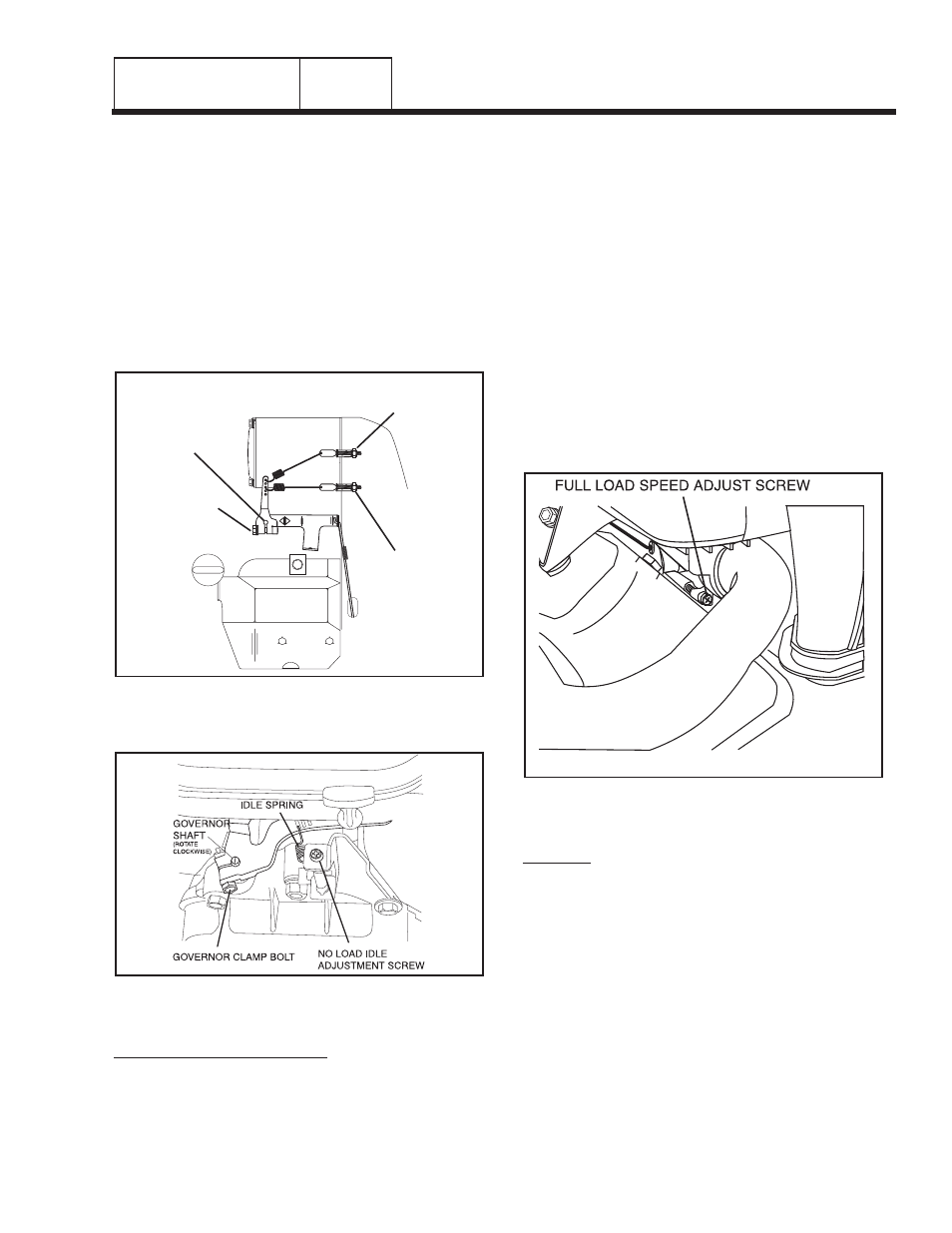
Figure 9. Engine Governor Adjustment Single
Cylinder Engines
Figure 10. Engine Governor Adjustment
V-twin Engines
PROCEDURE (12/15 KW UNITS):
1. Loosen governor clamp bolt (See Figure 10).
2. Completely remove the idle spring.
3. With governor arm at wide open throttle position, rotate
governor shaft fully clockwise. Tighten clamp bolt to 84
inch-pounds.
4. Start unit and apply full load. Use full load speed adjust
screw (Figure 11) to adjust frequency to 58 Hz.
5. Remove load, stop engine, loosen the idle adjust screw
and reconnect the idle spring.
6. Using your hand, push the governor arm to the closed
throttle position. Make sure the idle spring does not
stretch at all.
7. Restart the unit.
8. Slowly turn the idle adjust screw to adjust the no-load
idle speed to 62.5 Hz.
9. The governor is now set.
Figure 11. Full Load Speed Adjust
Screw V-twin Engines
RESULTS:
1. If, after adjusting the engine governor, frequency and
voltage are good, tests may be discontinued.
2. If frequency is now good, but voltage is high or low, go to
Test 13.
3. If engine was overspeeding, check linkage and throttle
for binding. If no governor response is indicated refer to
engine service manual.
4. If engine appears to run rough and results in low
frequency, proceed to Problem 11, Section 4.3.
GOVERNOR
SHAFT
PRIMARY
ADJUST
SCREW
GOVERNOR
CLAMP
BOLT
SECONDARY
ADJUST SCREW
PART 2