Bryant ASPAS1BBA015 User Manual
Page 69
Page 69
SECTION 3.4
DIAGNOSTIC TESTS
“V-TYPE” PREPACKAGED
TRANSFER SWITCHES
RESULTS:
If a short is indicated in steps 5 through 9, repair
wiring and re-test. If utility line to line voltage is
measured in Step 14, proceed to Test 35.
TEST 35 - CHECK TRANSFORMER (TX)
DISCUSSION:
The transformer is a step down type and has two
functions. It supplies approximately 16VAC to the
control board for utility sensing. It also supplies
approximately 16 VAC to the battery charger when
utility is available for trickle charge. A shorted
transformer can result in fuse F1 or F2 blowing.
PROCEDURE:
1. On the generator panel, set the Auto-Off-manual switch
to OFF.
2. Turn off the utility power supply to the transfer switch,
using whatever means is provided.
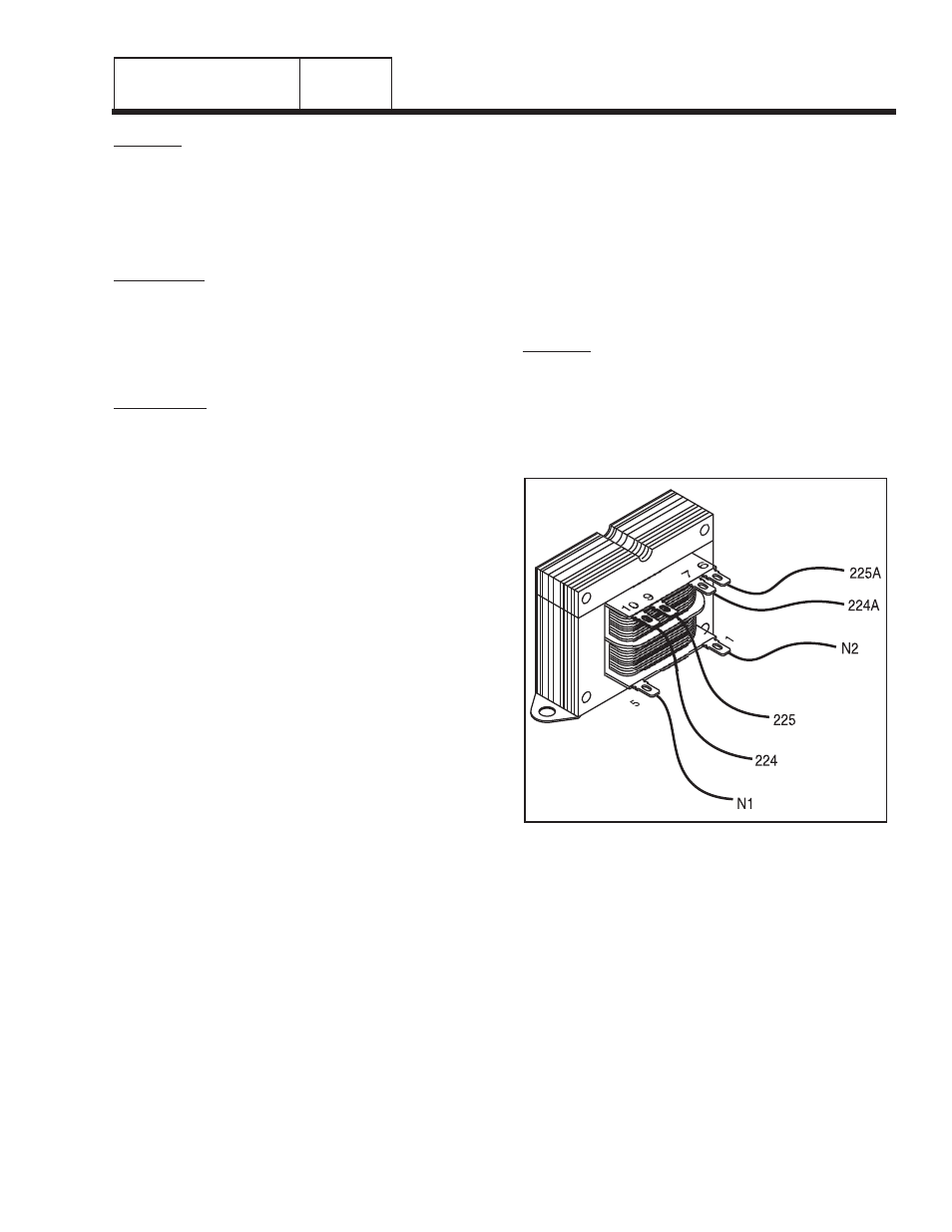
3. See Figure 6. Disconnect Wires N1, N2, 224, 225,
224A, 225A from transformer (TX).
4. Set a VOM to the "R x 1" scale.
5. Connect one test lead to TX terminal 1. Connect the
other test lead to TX terminal 5. Approximately 38.5
ohms should be measured
6. Connect one test lead to TX terminal 10. Connect the
other test lead to TX terminal 9. Approximately 1.5
ohms should be measured.
7. Connect one test lead tot TX terminal 7. Connect the
other test lead to TX terminal 6. Approximately 0.3
ohms should be measured.
8. Connect one test lead to TX terminal 1. Connect the
other test lead to the transformer case. INFINITY
should be measured.
9. Connect one test lead to TX terminal 7. Connect the
other test lead to the transformer case. INFINITY
should be measured.
10.Connect one test lead to TX terminal 9. Connect the
other test lead to the transformer case. INFINITY
should be measured.
11.Connect one test lead to TX terminal 1. Connect the
other test lead to TX terminal 10. INFINITY should be
measured.
12.Connect one test lead to TX terminal 1. Connect the
other test lead to TX terminal 7. INFINITY should be
measured.
13.Connect one test lead to TX terminal 10. Connect the
other test lead t TX terminal 7. INFINITY should be
measured.
RESULTS:
For steps 5, 6, and 7, replace transformer if an open
is indicated, or if the resistance value indicated is
zero. If the resistance value is not within the
approximate range, proceed to test 65.
For steps 8 through 13, replace the transformer if it
fails any of these steps.
Figure 6. Transformer (TX)
PART 3