Operational analysis, Part 4, Page 83 – Bryant ASPAS1BBA015 User Manual
Page 83
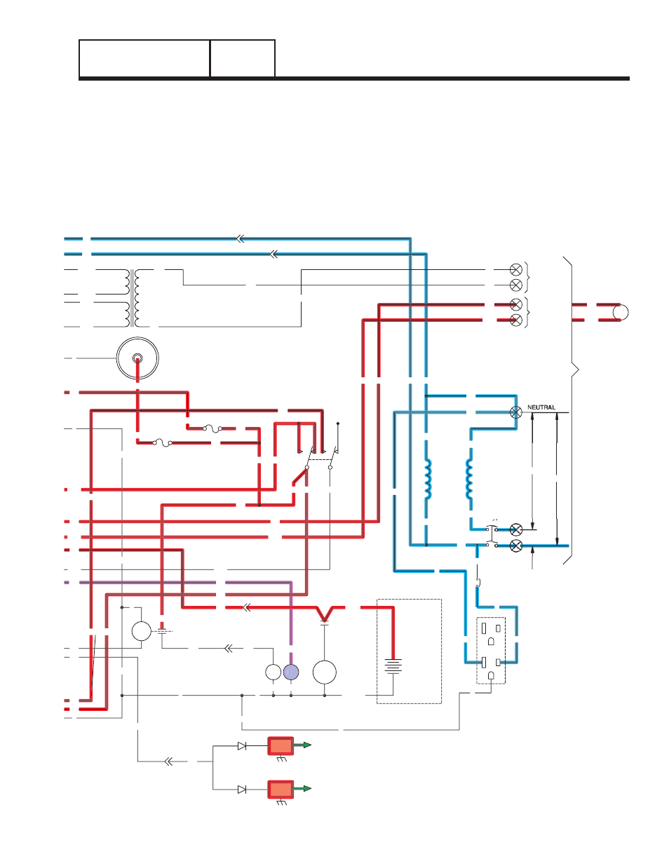
• The "engine warm-up timer" will run for about 15
seconds. When this timer finishes timing, board
action will initiate transfer to the "Standby" power
source. As shown in Figure 4 (above), the timer is
still running and transfer has not yet occurred.
• Generator AC output is available to transfer switch
terminal lugs E1/E2 and to the normally open
contacts of a transfer relay. However, the transfer
relay is de-energized and its contacts are open.
F1
SM
C1-1
15
0
0
18
C1-5
56
18
17
15
17
15A
SCR
0
0
0
15
16
239
15
14
0
194
23
13
18
D
IM2
IM1
SP2
SP1
23
16
0
13
SC
0
SW1
15
15A
239
194
FS
0
14
C2-1
WINDING
(STATOR)
POWER
22
44
11
CB1
33
56VA
1VA
13
225
225A
224A
224
TX
17
N1
N2
11
22
C2-5
N2
N1
C2-6
11
194
23
194
23
N1
N2
CUSTOMER
SUPPLIED
BATTERY
12V
BLACK
RED
SC
240V
120V
120V
CUSTOMER
CONNECTIONS
COIL
12Vdc
UTILITY
INPUT
240VAC
RELAY
TRANSFER
TR
12VDC ACCESSORY SOCKET
+
-
14
0
0
15
17
22
N
11
23
194
22
D
GFCI
OUTLET
EXTERNAL
G
G
G
L
N
L
11
G
G
N
N
CB3
N
0
0
15
15
15
13
15
15B
15B
F2
0
0
239
SECTION 4.2
OPERATIONAL ANALYSIS
DC CONTROL
PART 4
Page 83
Figure 4. Circuit Condition - Engine Startup and
Running