Test 4- fixed excitation test /rotor amp draw test, Diagnostic tests, Part 2 – Bryant ASPAS1BBA015 User Manual
Page 37
Page 37
SECTION 2.4
DIAGNOSTIC TESTS
AC GENERATORS
TEST 4- FIXED EXCITATION TEST
/ROTOR AMP DRAW TEST
DISCUSSION:
Supplying a fixed DC current to the rotor will induce a
magnetic field in the rotor. With the generator
running, this should create a proportional voltage
output from the stator windings.
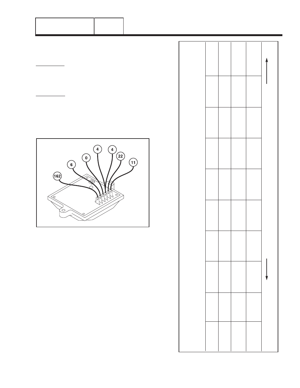
PROCEDURE:
1. Disconnect Wire 4 from the voltage regulator, 3rd
terminal from the top. See Figure 3.
2. Connect a jumper wire to the disconnected Wire 4 and
to the 12 volt fused battery supply Wire 15. (located at
15A fuse).
Figure 3. Voltage Regulator
3. Set VOM to AC volts.
4. Disconnect Wire 2 from the excitation circuit breaker
(CB2) and connect one meter test lead to that wire.
Disconnect Wire 6 from the voltage regulator and
connect the other meter test lead to that wire. (5th
terminal from top, double check wire number).
5. Set the AUTO-OFF-MANUAL switch to MANUAL. Once
the engine starts, record the AC voltage.
6. Set the AUTO-OFF-MANUAL switch to OFF. Reconnect
Wire 2 and Wire 6.
7. Disconnect Wire 11 from the voltage regulator and
connect one meter test lead to that wire. Disconnect
Wire 22 from the voltage regulator and connect the
other meter test lead to that wire (both wires are located
at the top two terminals of the voltage regulator, see
Figure 3).
PART 2
TEST 4 RESUL
TS - FIXED EXCIT
A
TION TEST/R
O
T
OR AMP DRA
W TEST
Results:
Size
ABCD
E
F
G
H
Voltage Results
ALL
Above 60 VAC
Above 60 VAC
Below 60 VAC
Zero or
Below 60 VAC
Below 60 VAC
Above 60 VAC
Below 60 VAC
Wire 2 & 6
Residual Volts
Voltage Results
ALL
Above 60 VAC
Below 60 VAC
Above 60 VAC
Zero or
Below 60 VAC
Below 60 VAC
Above 60 VAC
Below 60 VAC
Wire 11 & 22
Residual Volts
Static Rotor
6 & 7 kW
0.91-1.06A
0.91-1.06A
0.91-1.06A
Zero
Above 1.5A
0.91-1.06A
Zero
0.91-1.06A
Amp Draw
12 & 12 kW
0.80A
0.80A
0.80A
Current
Above 1.3A
0.80A
Current
0.80A
13 & 15 kW
0.64A
0.64A
0.64A
Draw
Above 1.1A
0.64A
Draw
0.64A
Running Rotor
6 & 7 kW
0.91-1.06A
0.91-1.06A
0.91-1.06A
Zero
Above 1.5A
0.91-1.06A
Zero
Above 1.5A
Amp Draw
12 & 12 kW
0.80A
0.80A
0.80A
Current
Above 1.3A
0.80A
Current
Above 1.3A
13 & 15 kW
0.64A
0.64A
0.64A
Draw
Above 1.1A
0.64A
Draw
Above 1.1A
MATCH
RESULTS
WITH
LETTER
AND REFER TO FLOW CHART IN SECTION 2.3 “Problem 1”