Specification of configuration switches – IDEC FS1A Controller User Manual
Page 23
2-14
Specification of configuration switches
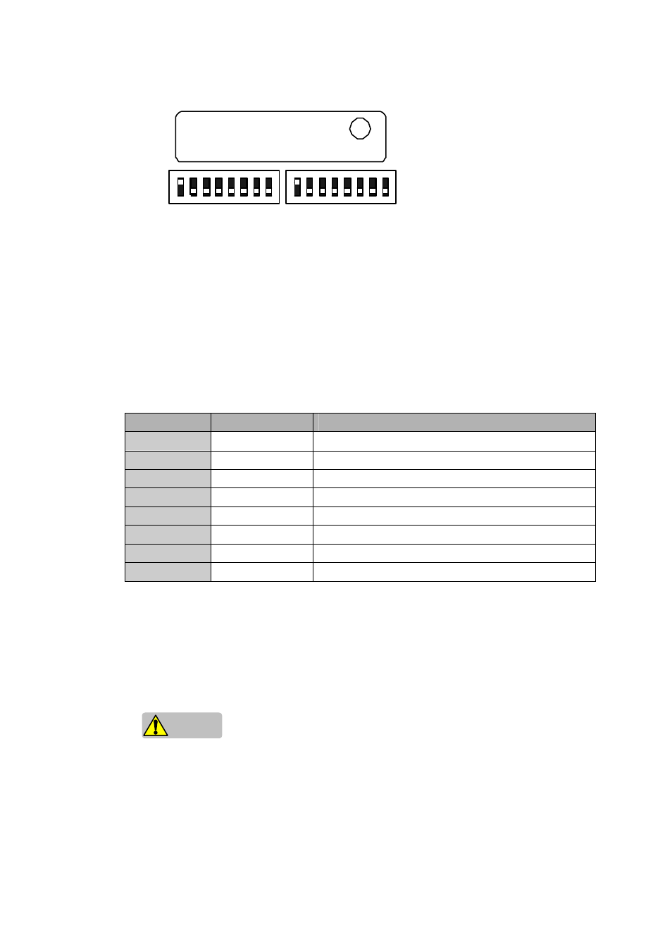
(1) Logic switch
The logic switch is an 8-digit DIP switch for use in logic configuration. When one of 8 digits is
selected, the corresponding logic in the SafetyOne is activated. See “Chapter 5 Logic” for
further information of each logic. The upper position of each digit is the ON state. Multiple
switches must not be selected.
(2) Timer switch
The timer switch is an 8-digit DIP switch for use in OFF-delay timer value configuration. When
one of 8 digits is selected, the delay time at shut-off operation is activated. The upper position of
each digit is ON state. Multiple switches must not be selected.
Switch
(Indication)
Descriptions
0
1
No OFF-delay (safety outputs shut OFF immediately)
.1
2
OFF-delay timer 0.1s
.5
3
OFF-delay timer 0.5s
1
4
OFF-delay timer 1s
2
5
OFF-delay timer 2s
5
6
OFF-delay timer 5s
15
7
OFF-delay timer 15s
30
8
OFF-delay timer 30s
(3) Enter button
The enter button is used to activate the configuration of logic and timer value. Error LED will
blink for 1 to 5 seconds after pressing the enter button. Releasing the button during blinking
activates the setting. The blinking LED becomes ON if the button is pressed for more than 5
seconds, and the setting becomes invalid even after the button is released.
Caution
For setting the swithes and enter button, use the configuration tool supplied with the Safetyone.
(1) (2)
(1) Logic switch
(2) Timer switch
(3) Enter button
(3)
LOGIC No.
TIMER (S)
ENTER
0 .1 .5 1 2 5 15 30
1 2 3 4 5 6 7 8