IDEC FS1A Controller User Manual
Page 120
5-79
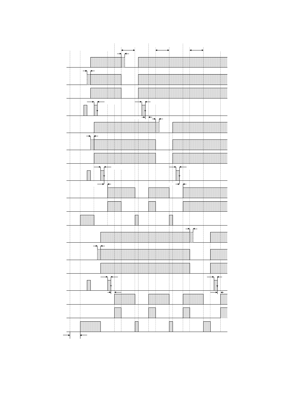
Safety input : X0
Safety output 1 :
Y0,Y1
Monitor output for
X0 and X1 : Y4
Control start input
: X12
Solenoid output:
Y17
Power ON
Off delay
time
(X4, X5, X10, X11 are ON in this chart.)
Safety input : X2
Safety input : X6
Control start input
: X12
Safety output 2 :
Y2,Y3
Monitor output for
safety output 2 :
Y13
Solenoid output:
Y20
Safety output 1
ON
Safety output
all ON
Safety output
all ON
Monitor output for
X2 and X3 : Y5
Monitor output for
X6 and X7 : Y7
Off delay
time
Off delay
time
Safety output 2
ON
2. Example of control start inputs (X16, X17) which
are detected adhesion of the start switch on a partial stop.
Control start input
: X16
Control start input
: X17
Safety output 2
ON
0.1s...5s
0.1s...5s
0.1s...5s
Max 6s
Safety input : X1
Safety input : X3
(Note 1)
(Note 1)
(Note 1)
Safety input : X7
Note 1: When the input time difference of the dual channel safety inputs is 0.5s or more, an input monitor error is detected.
Refer to the following "Logic functions" for details.
Note 2: Example to turn on a control start input (X12) before turning on a control start input (X16).
(Note 1)
(Note 1)
(Note 1)
Max. 0.1s
Max. 0.1s
0.1s...5s
Max. 0.1s
Max. 0.1s
0.1s...5s
Max. 0.1s
Initialization
(Note 2)
0.1s...5s