Henny Penny OFG-391 User Manual
Page 37
Model OFG- 391
2-20. FLAME SENSOR
The flame sensor should glow a bright red when the pilot is lit and
ASSEMBLY
allows the gas valve to open. If it does not sense a flame, it
shuts down the gas valve.
Replacement
1. Remove electrical power supplied to the unit.
To avoid electrical shock or property damage, move the
power switch to OFF and disconnect main circuit
breaker, or unplug cord at wall receptacle.
2. Remove the control panel as discussed in the Complete Control
Panel Section..
3. Pull the wire off of the terminal of the flame sensor.
4. Using Phillips head screwdriver, remove the screw securing the
flame sensor assembly, and remove the assembly from the unit.
5. Replace with new assembly in reverse order. Make sure the
flame sensor has 1/4” gap between it and the pilot hood.
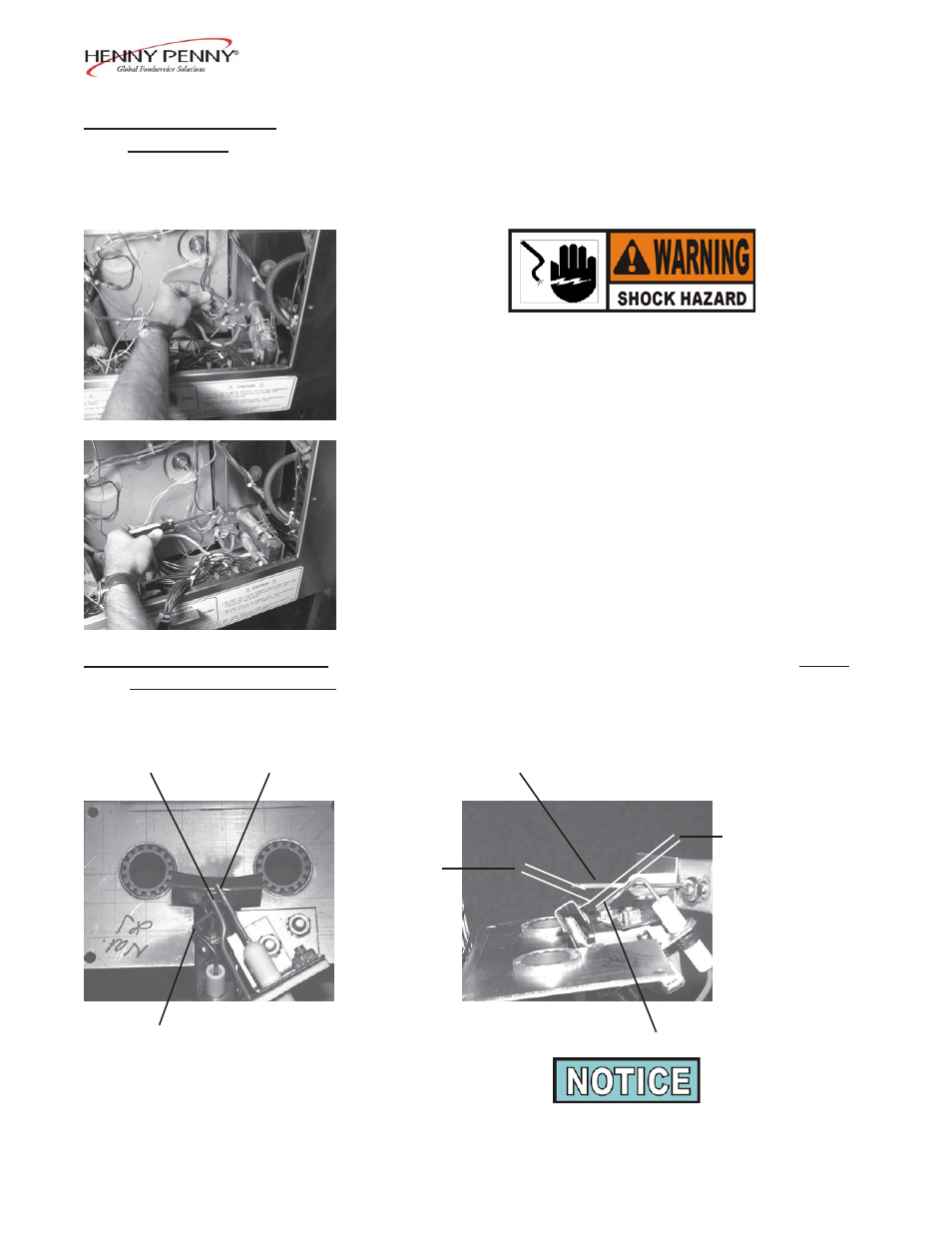
2-21. IGNITOR AND FLAME
For the proper function of the ignitor and flame sensor it is critical
SENSOR ADJUSTMENT
that they are at the adjusted properly. The flame rectification, from
the flame sensor to the module, should at least be 1.3 microamps.
See photos.
Ground Rod Flame Sensor
Flame Sensor
1/8 in. (.32 cm.)
1/4 in.
(.63 cm.)
Spark Electrode
Spark Electrode
If the burner assembly is removed from the cooker to install and
adjust the parts, once the assembly is re-installed, check the
spacing of the components again.
305
2-20