EnGenius Technologies EOA7530 User Manual
Page 10
3 Installation
This chapter describes how to install the EOA7530. It also describes the EOA7530 LEDs.
3.1 Installing the EOA7530
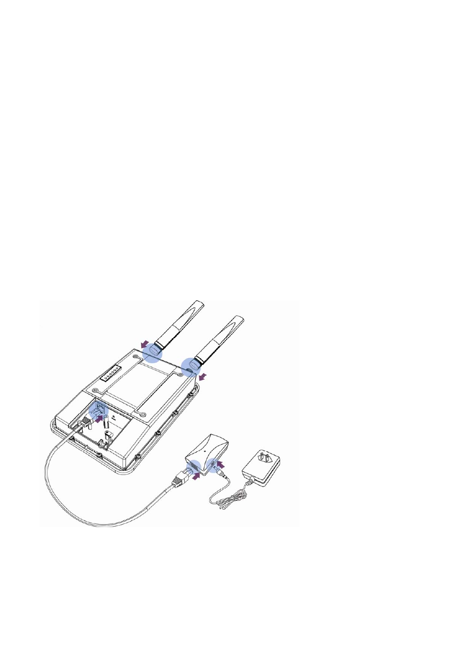
To install the EOA7530, use the following procedure and refer to the figure below.
1. Connect the two dipole antennas to the top of the EOA7530 and tighten them by hand.
2. Unscrew the compartment door on the bottom of the EOA7530 and remove the
compartment door to expose the RJ‐45 jack and Reset switch. Connect either end of an
Ethernet cable to the EOA7530 jack labeled RJ‐45. Connect the other end of the cable to
the RJ‐45 jack on the PoE adapter labeled AP/Bridge Network.
3. Attach the round plug on the supplied power adapter to the DC48 V IN connector on the
Power on Ethernet adapter. Connect the other end to a working AC outlet. The red LED
on the PoE adapter goes ON to show it is receiving AC power.
WARNING: Only use the power adapter supplied with the EOA7530. Using a different power adapter
can damage the EOA7530.
3.2 Understanding the EOA7530 LEDs
The EOA7530 has LEDs that show the operating status of the device. The following table describes
9