Memory locations and replacement procedures – Enterasys Networks Enterasys Gold Distributed Forwarding Engine 4G4285-49 User Manual
Page 81
Memory Locations and Replacement Procedures
Enterasys Matrix DFE-Gold Series PoE Module Hardware Installation Guide B-3
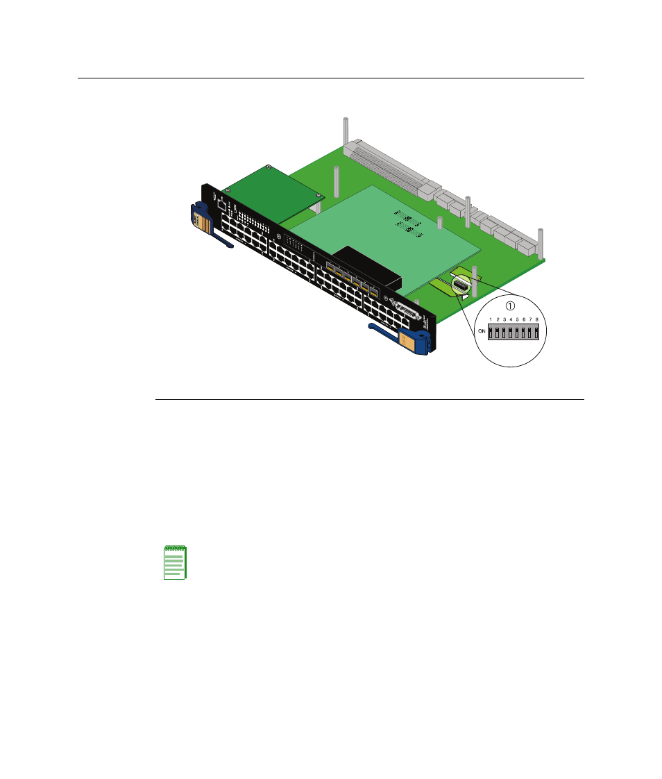
Figure B-1 Mode Switch Location (4G4285-49 shown without safety cover)
Memory Locations and Replacement Procedures
If the Dual in Line Memory Module (DIMM) or DRAM Single In‐line Memory Module
(SIMM) (FLASH memory) needs to be replaced, the following sections describe how to
access, locate, and replace these memory modules. If you have questions concerning the
replacement of either memory module, refer to “
” on page xviii for details
on how to contact Enterasys Networks.
shows the DIMM and DRAM SIMM locations on the main PC board.
1 Mode switch pack (4G4285-49 shown without safety cover)
uses the 4G4285-49 as an illustration, the location of the DIMM
and DRAM SIMM are the same on the 4G4205-72.