ProSoft Technology MVI56-DFCMR User Manual
Page 68
MVI56-DFCMR ♦ ControlLogix Platform
Reference
DF1 Interface Module with Reduced Data Block
Page 68 of 113
ProSoft Technology, Inc.
October 20, 2008
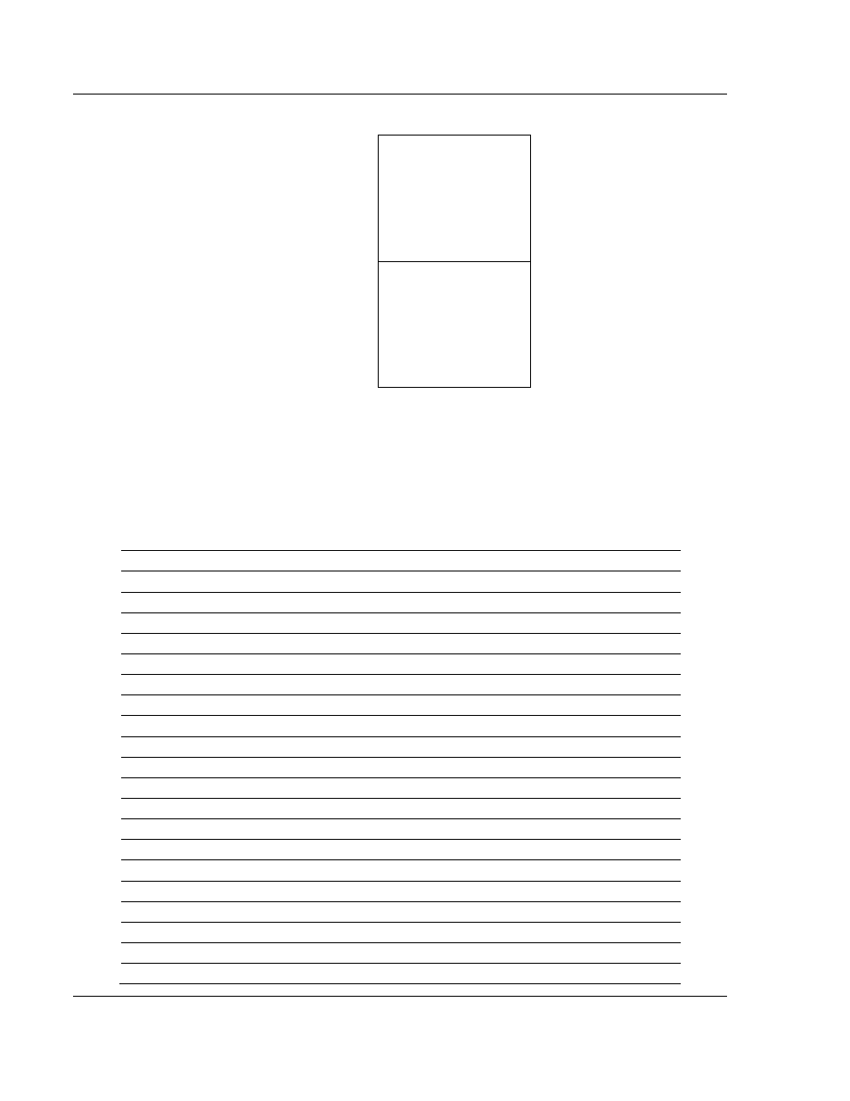
Module's Internal Database Structure
5000 registers for user data
0
Register Data
4999
3000 words of configuration and
status data
5000
Status and Config
7999
Data contained in this database is paged through the input and output images by
coordination of the ControlLogix ladder logic and the MVI56-DFCMR module's
program. Up to 42 words of data can be transferred from the module to the
processor at a time. Up to 42 words of data can be transferred from the
processor to the module. The read and write block identification codes in each
data block determine the function to be performed or the content of the data
block. The module uses the following block numbers:
MVI56-DFCMR Block Assignments
Block Range
Descriptions
-1
Status data block
0
Status data block
1 to 250
Read or write data
1000
Event Port 1
2000
Event Port 2
3000 to 3001
Port 1 slave polling control
3002 to 3009
Port 1 slave status
3100 to 3101
Port 2 slave polling control
3102 to 3109
Port 2 slave status
5001 to 5006
Port 1 command control
5101 to 5106
Port 2 command control
6000 to 6033
Port 1 commands (sent to module)
6100 to 6133
Port 2 commands (sent to module)
7000 to 7004
Port 1 Override File Maps (Sent to module)
7100 to 7104
Port 2 Override File Maps (Sent to module)
9000
Backplane Configuration data (sent to module)
9001
DFCM Port 1 Configuration (sent to module)
9002
DFCM Port 2 Configuration (sent to module)
9998
Warm-boot control block
9999
Cold-boot control block