ProSoft Technology MVI56-DFCMR User Manual
Page 67
Reference MVI56-DFCMR
♦ ControlLogix Platform
DF1 Interface Module with Reduced Data Block
ProSoft Technology, Inc.
Page 67 of 113
October 20, 2008
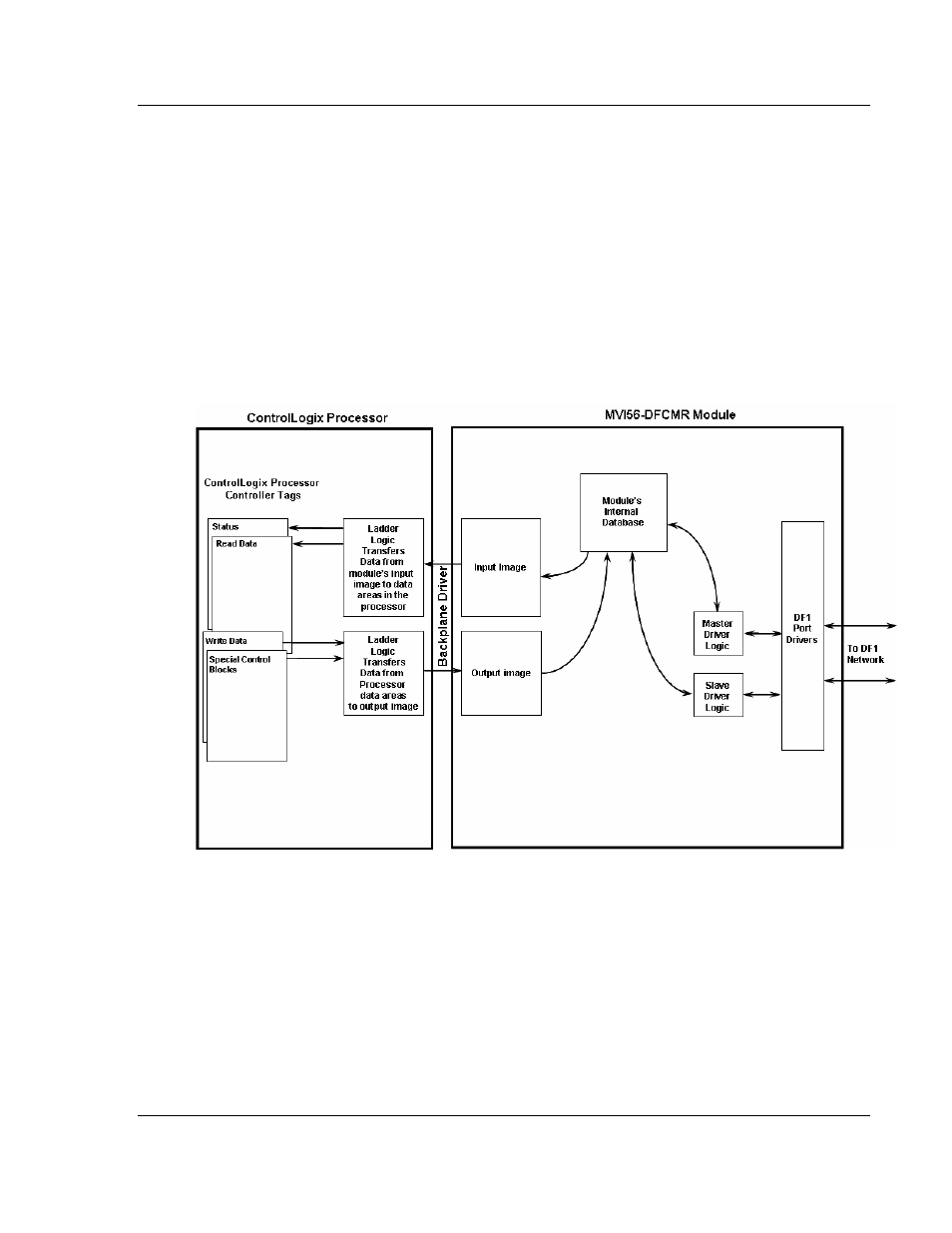
This bi-directional transference of data is accomplished by the module filling in
data in the module's input image to send to the processor. Data in the input
image is placed in the controller tags in the processor by the ladder logic. The
input image for the module is set to 42 words. This smaller data area permits fast
throughput of data between the module and the processor as well as easier
setup of the module in RSNETWORX.
The processor inserts data in the module's output image to transfer to the
module. The module's program extracts the data and places it in the module's
internal database. The output image for the module is also set to 42 words.
The following illustration shows the data transfer method used to move data
between the ControlLogix processor, the MVI56-DFCMR module, and the DF1
network.
All data transferred between the module and the processor over the backplane is
through the input and output images. Ladder logic must be written in the
ControlLogix processor to interface the input and output image data with data
defined in the controller tags. All data used by the module is stored in its internal
database. The following illustration shows the layout of the database.