2 illustration of stp – PLANET WGSW-2620HP User Manual
Page 103

User’s Manual of WGSW-2620HP
4.8.2 Illustration of STP
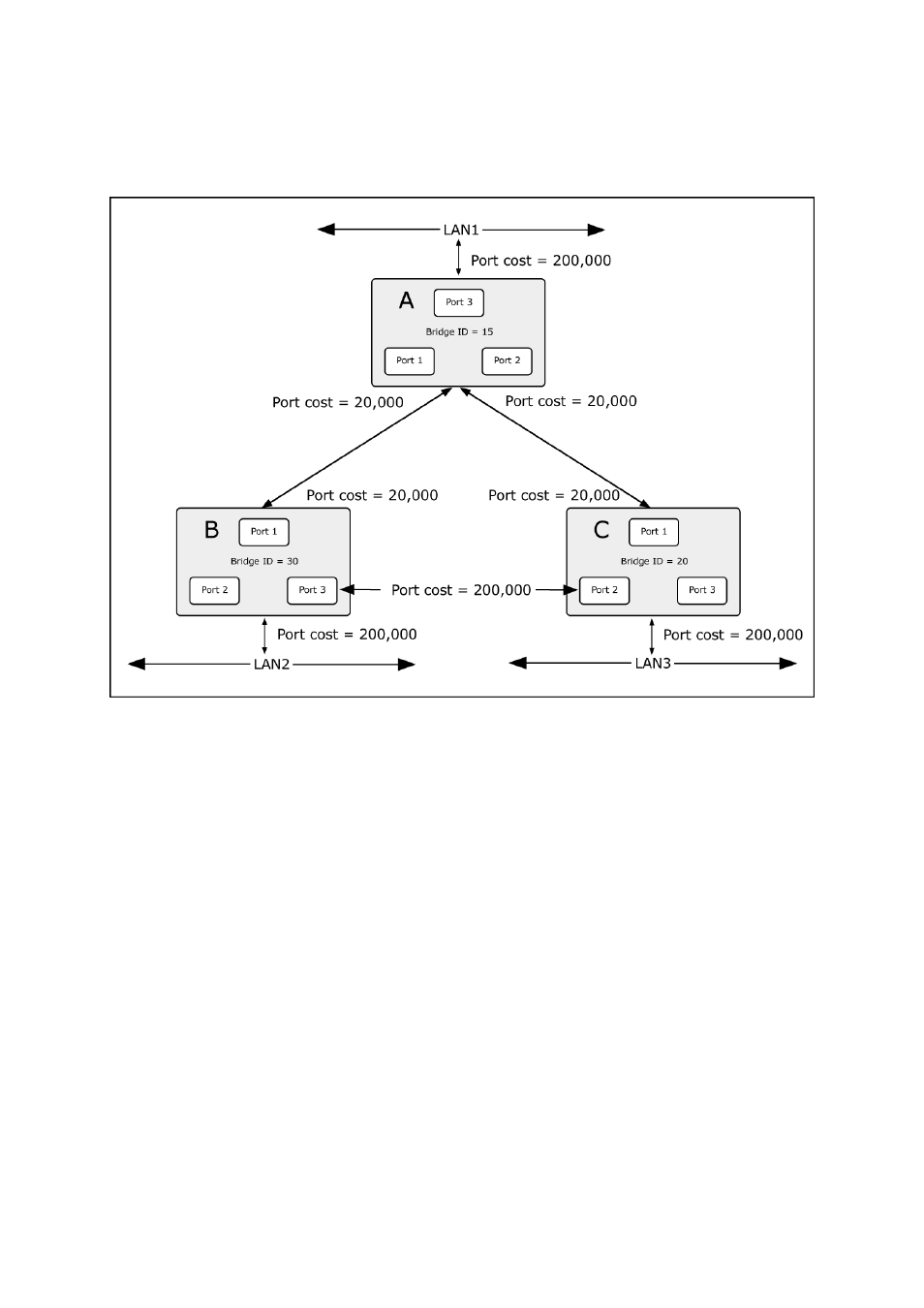
A simple illustration of three switches connected in a loop is depicted in the below diagram. In this example, you can
anticipate some major network problems if the STP assistance is not applied.
Figure 4-8-2:
Before Applying the STA Rules
If switch A broadcasts a packet to switch B, switch B will broadcast it to switch C, and switch C will broadcast it to back to
switch A and so on. The broadcast packet will be passed indefinitely in a loop, potentially causing a network failure. In this
example, STP breaks the loop by blocking the connection between switch B and C. The decision to block a particular
connection is based on the STP calculation of the most current Bridge and Port settings.
Now, if switch A broadcasts a packet to switch C, then switch C will drop the packet at port 2 and the broadcast will end
there. Setting-up STP using values other than the defaults, can be complex. Therefore, you are advised to keep the default
factory settings and STP will automatically assign root bridges/ports and block loop connections. Influencing STP to choose
a particular switch as the root bridge using the Priority setting, or influencing STP to choose a particular port to block using
the Port Priority and Port Cost settings is, however, relatively straight forward.
In this example, only the default STP values are used.
The switch with the lowest Bridge ID (switch C) was elected the root bridge, and the ports were selected to give a high port
cost between switches B and C. The two (optional) Gigabit ports (default port cost = 20,000) on switch A are connected to
one (optional) Gigabit port on both switch B and C. The redundant link between switch B and C is deliberately chosen as a
100 Mbps Fast Ethernet link (default port cost = 200,000). Gigabit ports could be used, but the port cost should be
increased from the default to ensure that the link between switch B and switch C is the blocked link.
103
