Layout of the megaraid sas 8408e raid controller, Sas 8408e raid controller – jumpers and connectors, Figure 3.6 – Avago Technologies MegaRAID SAS 8204ELP User Manual
Page 64: Table 3.6
3-14
MegaRAID SAS RAID Controller Characteristics
Copyright © 2005-2007 by LSI Logic Corporation. All rights reserved.
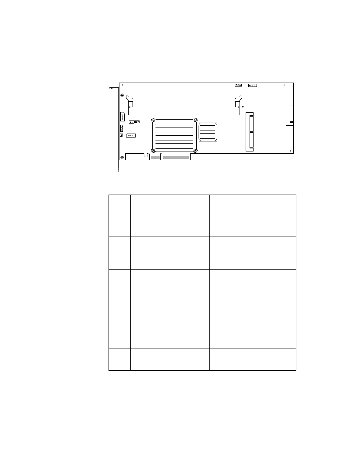
Figure 3.6
Layout of the MegaRAID SAS 8408E RAID Controller
Table 3.6
SAS 8408E RAID Controller – Jumpers and
Connectors
Jumper Description
Type
Comments
J1
Universal
Asynchronous
Receiver/Transmitter
(UART) debugging
3-pin
connector
Reserved for LSI Logic internal use.
J3
GND connector
1-pin
connector
Reserved for LSI Logic internal use.
J4
Ports 4–7
x4 SAS
ports
A SAS 4i connector that connects to
physical drives and expanders.
J5
Keyed I
2
C connector 3-pin
connector
Provides support for enclosure
management.
Reserved for LSI Logic internal use.
J6
On-board BIOS
Enable
2-pin
connector
The optional BIOS function is enabled
or disabled in software depending on
the status of this jumper.
No jumper: BIOS is enabled (default).
Jumper: BIOS is disabled.
J7
Firmware
initialization
mode 0 or 3 Select
2-pin
connector
Reserved for LSI Logic internal use.
J9
Unkeyed I
2
C
connector
3-pin
connector
Provides support for enclosure
management.
Reserved for LSI Logic internal use.
J3
J5
U11
U13
P1
J1
J9
J12
J6
J10
J7
J4
J11
J18
J15
Ports
Ports
4–7
0–3
- MegaRAID SAS 8204ELP (Channel) MegaRAID SAS 8204XLP MegaRAID SAS 8204XLP (Channel) MegaRAID SAS 8208ELP MegaRAID SAS 8208ELP (Channel) MegaRAID SAS 8208XLP MegaRAID SAS 8208XLP (Channel) MegaRAID SAS 8300XLP MegaRAID SAS 8308ELP MegaRAID SAS 8344ELP MegaRAID SAS 84016E MegaRAID SAS 84016E (Channel) MegaRAID SAS 8408E MegaRAID SAS 8480E MegaRAID SAS 8704ELP (Channel) MegaRAID SAS 8704EM2 MegaRAID SAS 8704EM2 (Channel) MegaRAID SAS 8708ELP (Channel) MegaRAID SAS 8708EM2 MegaRAID SAS 8708EM2 (Channel)