Layout of the megaraid sas 8308elp raid controller, Figure 3.4, Table 3.4 – Avago Technologies MegaRAID SAS 8204ELP User Manual
Page 58
3-8
MegaRAID SAS RAID Controller Characteristics
Copyright © 2005-2007 by LSI Logic Corporation. All rights reserved.
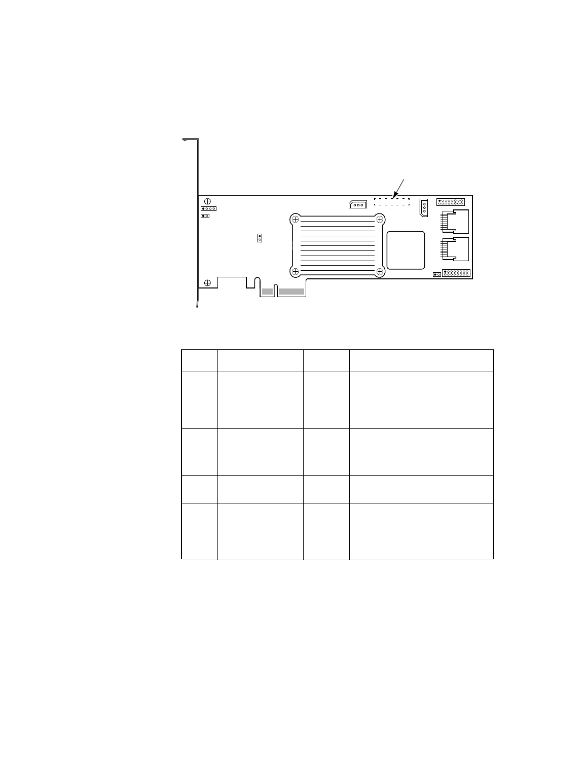
Figure 3.4
Layout of the MegaRAID SAS 8308ELP RAID Controller
Table 3.4
SAS 8304ELP RAID Controller and SAS 8308ELP RAID
Controller – Jumpers and Connectors
Jumper Description
Type
Comments
J1
IPMI-style I
2
C Debug
header (Intelligent
Platform
Management
Interface)
3-pin
connector
Used for diagnostic purposes.
J2
Individual Activity
LED header for all
eight ports
16-pin
(8x2)
jumper
Provides an LED interface
individually to eight SAS ports. The
LED indicates activity on particular
ports.
J3
Debugger
2-pin
jumper
Used for diagnostic purposes.
J4
Serial header for
debug use
4-pin
jumper
Used for diagnostic purposes.
Note: The serial port is not
compliant with the RS232
voltage level standard.
J3
J10
Ports
J9
P1
U13
Ports
J8
J1
J4
J5
J6
J7
J2
U14
0–3
4–7
J11
Connector Located
on Back of Board
- MegaRAID SAS 8204ELP (Channel) MegaRAID SAS 8204XLP MegaRAID SAS 8204XLP (Channel) MegaRAID SAS 8208ELP MegaRAID SAS 8208ELP (Channel) MegaRAID SAS 8208XLP MegaRAID SAS 8208XLP (Channel) MegaRAID SAS 8300XLP MegaRAID SAS 8308ELP MegaRAID SAS 8344ELP MegaRAID SAS 84016E MegaRAID SAS 84016E (Channel) MegaRAID SAS 8408E MegaRAID SAS 8480E MegaRAID SAS 8704ELP (Channel) MegaRAID SAS 8704EM2 MegaRAID SAS 8704EM2 (Channel) MegaRAID SAS 8708ELP (Channel) MegaRAID SAS 8708EM2 MegaRAID SAS 8708EM2 (Channel)