6 terminations, 7 cooling, Terminations -29 – KEPCO RA 19-4C Operator Manual User Manual
Page 47: Cooling -29
RA 19-4C 121013
2-29
2.5.2.3
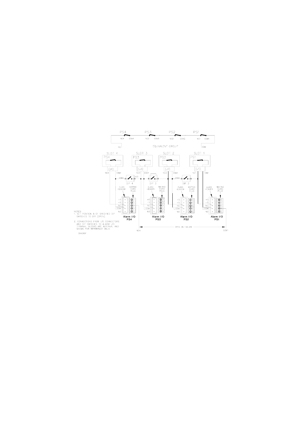
OPEN ON FAILURE USING EXTERNAL WIRING OF I/O ALARM TERMINAL BLOCKS
Figure 2-18 illustrates an open on failure alarm configuration using external wiring of the I/O
mating connectors for four power supplies. It is necessary to set DIP switch position 8 to OFF
(open) for each slot included in the open on failure alarm circuit.
FIGURE 2-19. OPEN ON FAILURE ALARM CONFIGURATION USING EXTERNAL WIRING
AT I/O ALARM TERMINAL BLOCKS, SIMPLIFIED DIAGRAM
2.6
TERMINATIONS
All input, output and control terminations are located on the rear panel of the rack adapter (see
Figure 1-4).
2.7
COOLING
The HSF power supplies installed in the rack adapter are maintained within their operating tem-
perature range by means of cooling fans within the power supplies. ALL OPENINGS AROUND
THE RACK ADAPTER CASE MUST BE KEPT CLEAR OF OBSTRUCTION TO ENSURE
PROPER AIR CIRCULATION. Care must be taken that the ambient temperature, which is the
temperature of the air immediately surrounding the rack adapter, does not rise above the speci-
fied limits for the operating load conditions of the installed HSF power supplies. Kepco recom-
mends providing additional space above and below the rack adapter where possible when the
rack adapter is fully populated.