External wiring, simplified diagram -6 – KEPCO RA 19-4C Operator Manual User Manual
Page 24
2-6
RA 19-4C 121013
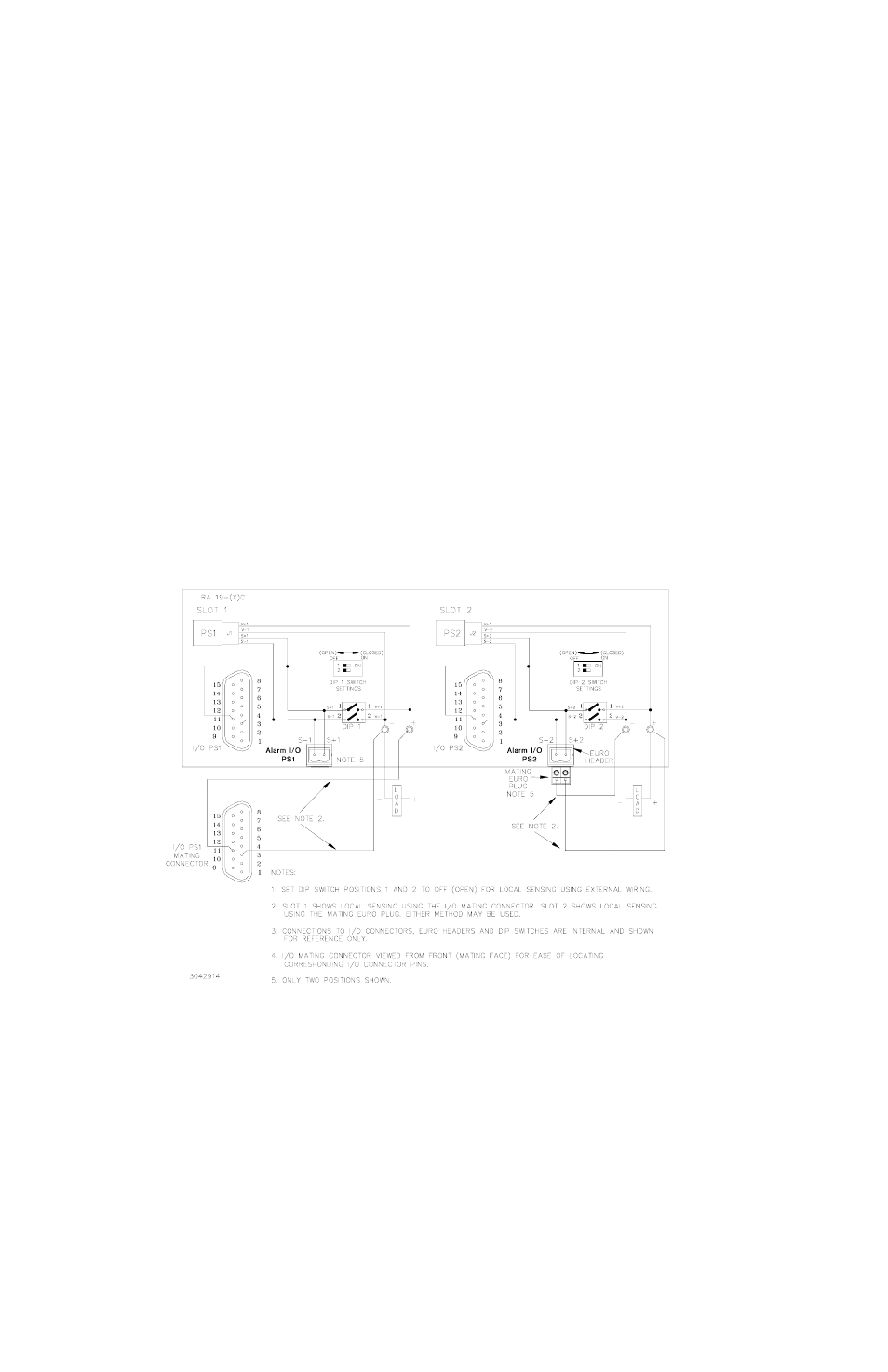
2.4.1.2.2 INDEPENDENT OPERATION - LOCAL SENSING USING EXTERNAL WIRING
To configure a slot for local sensing using external wiring, first set internal DIP switch positions 1
and 2 of the DIP switches associated with that slot to OFF (open).
External local sensing is accomplished by connecting (V+) to (S+) and (V–) to (S–). This can be
done at either the mating I/O connector supplied (see Table 2-1) or the DC OUTPUT terminal
block. See Figure 1-3 for DIP socket locations. Figure 1-3 illustrates I/O connector pin assign-
ments. Figure 2-4 illustrates local sensing of PS1 and PS2 using external jumpers connected to
the I/O mating connector.
NOTE: The internal DIP switch settings established at the factory for positions 1 and 2 of the
associated DIP switch MUST be changed to OFF (open) if this option is chosen.
Positions 3 and 4 (connecting sense lines in parallel) and Position 5 (current share) must be set
to OFF. Configure Positions 6, 7, and 8 (alarms) per PAR. 2.5.
FIGURE 2-4. INDEPENDENT OPERATION, LOCAL SENSING FOR PS1 AND PS2 USING
EXTERNAL WIRING, SIMPLIFIED DIAGRAM