3 series connection, Ar. 2.4.3 – KEPCO RA 19-4C Operator Manual User Manual
Page 37
RA 19-4C 121013
2-19
2.4.3
SERIES CONNECTION
HSF power supplies may be connected in series to obtain higher output voltages. The RA 19-
4C rack adapter is designed to safely handle a maximum output voltage of 500 Volts; contact
Kepco Applications Engineering for additional information. The power supply with the lowest
rated value of maximum current establishes the maximum load current allowed. Series configu-
rations can only be accomplished by external wiring of the I/O mating connector.
For series operation, connect (+) and (–) terminals at the DC OUTPUT terminal block of power
supplies to be connected in series. Bus bars are available as accessories to make these con-
nections when connecting adjacent slots in series (refer to Table 1-2).
The DC OUTPUT + terminal of one supply must be connected to DC OUTPUT – terminal of the
next supply. Each Power Supply in series must be protected by a diode connected in parallel
with the output as shown in Figure 2-11. The diode protects against reverse voltages. For con-
venience, bus bars are available as accessories to connect adjacent slots in series (refer to
Table 1-2). The bus bars can also serve as heat sinks for the diodes (see Figure 2-21). Protec-
tion diodes must conform to the following specifications:
• V
REV
> 2 x V
NOM
x N where V
NOM
is the output voltage of the HSF power supply and N
is the number of power supplies connected in series.
• I
FWD
> 1.5 x I
NOM
where I
NOM
is the output current of the HSF power supply.
Rack adapter DIP switches positions 1 through 5 must be set to OFF (open) on all DIP switches
between series-connected modules (refer to Figure 1-5).
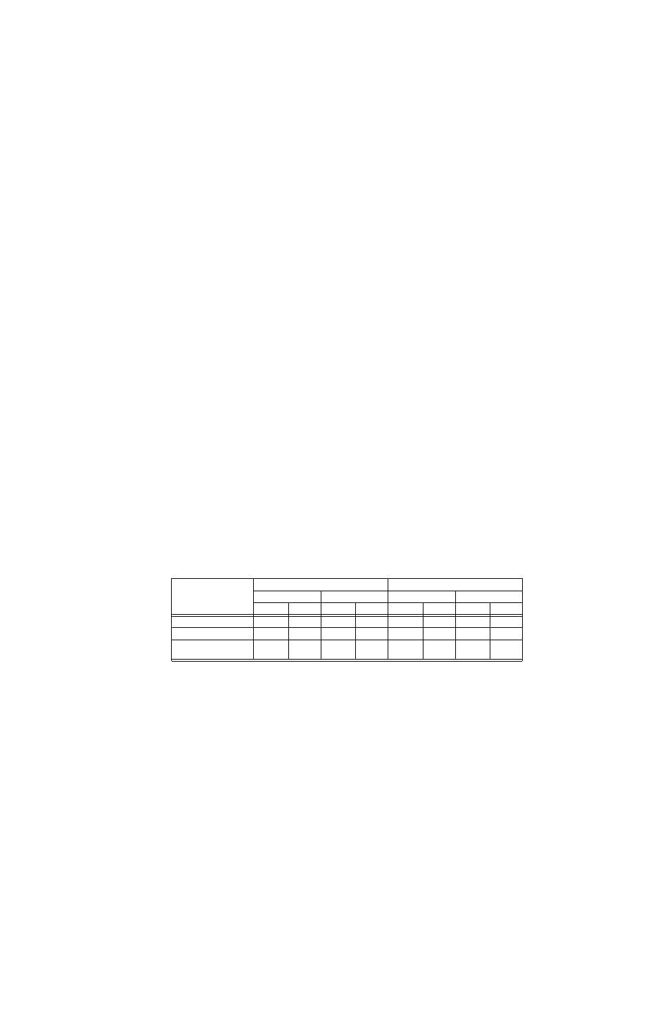
Table 2-4 lists the settings for the HSF DIP switches required to configure HSF power supplies
to use either local or remote control.
TABLE 2-4. HSF DIP SWITCH CONFIGURATION FOR VOLTAGE CONTROL OF
MULTIPLE UNITS IN SERIES
HSF DIP
SWITCH
POSITION
(See Note)
HSF 300W, 600W
HSF 1200W, 1500W
Vadj Control
External R or V
Vadj Control
External R or V
SW2
SW1
SW2
SW1
SW2
SW1
SW2
SW1
Position 1 (REF)
OFF
ON
ON
OFF
OFF
ON
ON
OFF
Position 2 (RV)
OFF
ON
ON
OFF
OFF
ON
ON
OFF
Position 7 (COM)
OFF
See
Note (2)
ON
See
Note (2)
OFF
ON
ON
OFF
NOTES:
(1) HSF DIP Switches are located at the rear of each HSF module; refer to appropriate HSF manual for location.
(2) For HSF 600W, set SW1 position 7 to OFF
For HSF 300W, SW1 position 7 allows the DC ON indicator to powered by an internal auxiliary supply (see HSF
300W Operator Manual for details).