1 independent operation, Independent operation -3, Ar. 2.4.1) – KEPCO RA 19-4C Operator Manual User Manual
Page 21
RA 19-4C 121013
2-3
2.4.1
INDEPENDENT OPERATION
The rack adapter is preconfigured at the factory for independent operation of all slots. DIP
switch positions 3 through 5 associated with each slot must be set to OFF (open) for each
power supply to be operated independently. HSF 300W and 600W modules must have sense
connections configured to work properly (see PAR. 2.4.1.2).
2.4.1.1
USING ONE POWER SUPPLY TO CONTROL MULTIPLE POWER SUPPLIES
Figure 2-2 shows the connection of three power supplies each having an independent load. In
this configuration the output voltage of all three power supplies is controlled by one power sup-
ply (master) and the current drawn by each power supply is determined by the respective load.
Refer to PAR. 2.4.2.1 to select local or remote voltage control.
The connections between RV and -COM may be made using the rack adapter DIP switches or
by wiring the I/O mating connector as shown in Figure 2-2. Using external wiring at the I/O mat-
ing connector allows configuration of non-adjacent slots. Use shielded wire for connections to
RV pins. HSF 300W and 600W modules MUST have sense connections configured to work
properly (see PAR. 2.4.1.2
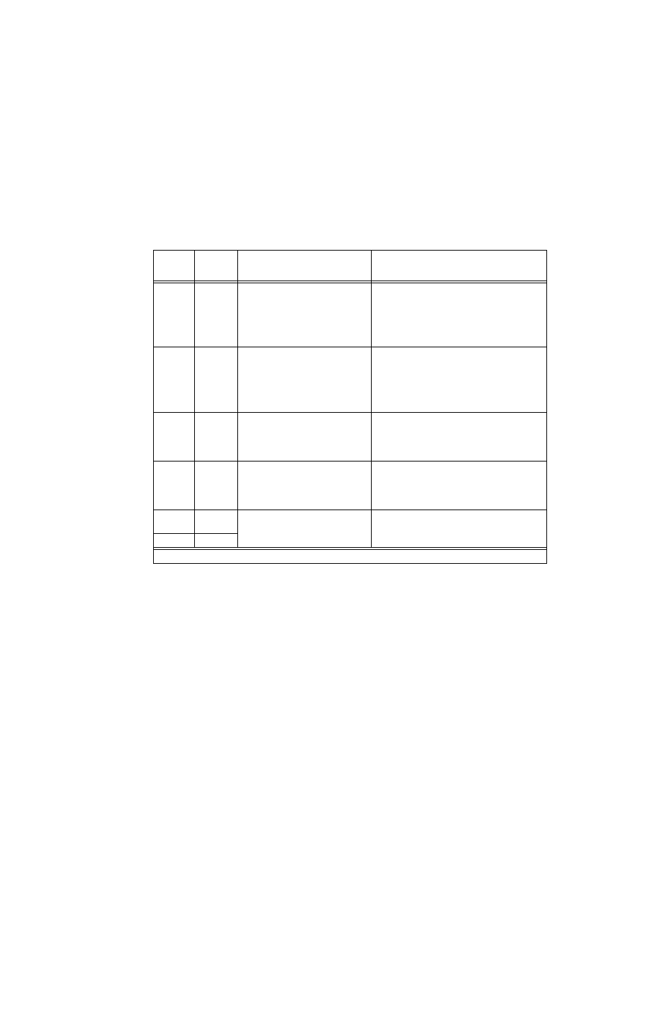
3, 4
(SEE NOTE)
Connect
Sense
+ and –
in parallel
Required ON for parallel configurations
using DIP switch settings to connect the
sense leads in parallel. Position 3 con-
nects +S to adjacent slot +S, Position 4
connects –S to adjacent slot –S (see
PAR.2.4.2.5.1 (DIP switches) and 2.4.2.5.2
(external wiring).
Position 3 and 4 required OFF (factory default) for all
configurations except parallel configurations using
DIP switch settings to connect the sense leads in
parallel.
5
Current
Balance
Required ON for parallel operation with
forced current share (connects current
share lines in parallel) unless connections
are made via external wires (see PAR.
2.4.2.4).
Required OFF (factory default) for
a) independent and series configurations.
b) Parallel configurations using external wires at I/O
connector to connect CSB (current share bus) lines
in parallel.
c. Parallel configurations without forced current
sharing (current balancing),
6, 7
Close on
Failure
Alarm
When set to ON, allows a single alarm to
provide failure indication (contact closure
between N.O. pin and COM pin) if any one
of many power supplies fails (see PAR.
2.5.1).
When set to OFF (factory default), individual power
supplies produce closure between I/O connector
N.O. and COM pins upon failure (see PAR. 2.5.1).
8
Open on
Failure
Alarm
When set to ON, allows a single alarm to
provide failure indication (contact open
between N.C. pin and COM pin) if any one
of many power supplies fails (see PAR.
2.5.2).
When set to OFF (factory default), individual power
supplies produce open between I/O connector N.C.
and COM pins upon failure (see PAR. 2.5.2).
9
Remote
Voltage
When both set to ON, enables control of
multiple supplies from power supply desig-
nated as the Master.
When both set to OFF allows independent voltage
control of each power supply
10
-Common
TABLE 2-2. REAR PANEL DIP SWITCH FUNCTIONS (CONTINUED)
DIP
SWITCH
POSITION
FUNCTION
DIP SWITCH SET TO ON (CLOSED)
DIP SWITCH SET TO OFF (OPEN)
NOTE: Positions 1, 2, 3, 4 not used for HSF 1200W and 1500W modules; leave in default position.