1 establishing key positions, Figure 2-1. ra 19-4c rack adapter keying, 4 slot configuration – KEPCO RA 19-4C Operator Manual User Manual
Page 20: Establishing key positions -2, Slot configuration -2, Ra 19-4c rack adapter keying -2, Rear panel dip switch functions -2
2-2
RA 19-4C 121013
2.3.1
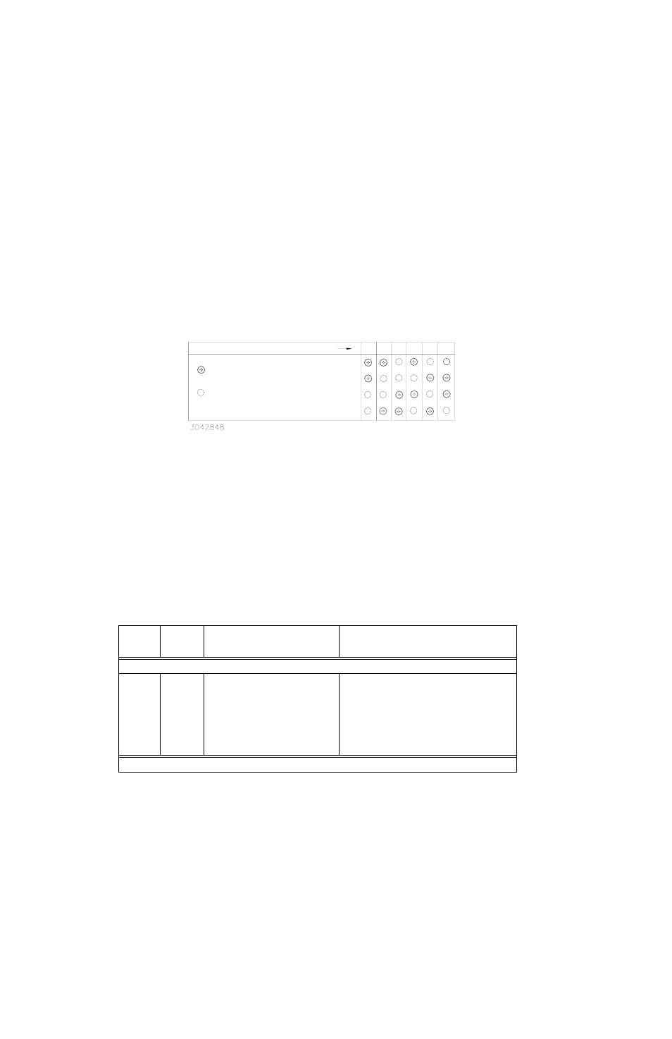
ESTABLISHING KEY POSITIONS
To establish the keying of any position, simply install the 4-40 x 0.75 in. thread-forming screws
(Kepco P/N 101-0480) into the corresponding holes as indicated in Figure 2-1. DO NOT OVER-
TIGHTEN these screws (max torque 5 in.-lbs. (0.6 N x m). DO NOT ALTER THE KEYING AT
THE POWER SUPPLY.
FIGURE 2-1. RA 19-4C RACK ADAPTER KEYING
2.4
SLOT CONFIGURATION
Configuring slots of the rack adapter for independent, parallel or series operation is accom-
plished either by means of DIP switches mounted on the rear panel associated with each slot
(see Figure 1-3), or externally by connecting the appropriate pins of the associated I/O mating
connector. DIP switch functions are explained in Table 2-2. The schematic diagram (Figure 1-
5), which shows all internal connections, is provided as a reference.
Slot configuration requires the following selection:
1. Select independent (PAR. 2.4.1), parallel (PAR. 2.4.2), or series (PAR. 2.4.3) operation.
2. Optional: Select close-on-failure or open-on-failure alarm (PAR. 2.5).
TABLE 2-2. REAR PANEL DIP SWITCH FUNCTIONS
DIP
SWITCH
POSITION
FUNCTION
DIP SWITCH SET TO ON (CLOSED)
DIP SWITCH SET TO OFF (OPEN)
NOTE: BOLD TYPE INDICATES FACTORY SETTINGS.
1, 2
(SEE NOTE)
Local /
Remote
Sensing
Selection
Required ON (factory default) for inde-
pendent operation with Local Sensing.
Position 1 connects V+ to S+, Position 2
connects V– to S– (see PAR. 2.4.1.2).
Position 1 and 2 required OFF for:
a) Independent configurations using Remote Sensing
(see PAR. 2.4.1.2).
b) Independent configurations using Local Sensing with
user supplied connections from V+ to S+ and V– to S–
(see PAR. 2.4.1.2).
c) All parallel configurations (sensing must be estab-
lished using external wires) (see PAR. 2.4.2.5).
d) All series connections (see PAR. 2.4.3).
NOTE: Positions 1, 2, 3, 4 not used for HSF 1200W and 1500W modules; leave in default position.
= SCREW TO BE INSTALLED
AT REAR PANEL.
= NO SCREW INSTALLED.
DESIRED VOLTAGE
5V 12V 15V 24V 28V 48V