1 open on failure using rear panel dip switches, Open on failure using rear panel dip switches -26 – KEPCO RA 19-4C Operator Manual User Manual
Page 44
2-26
RA 19-4C 121013
2.5.2.1
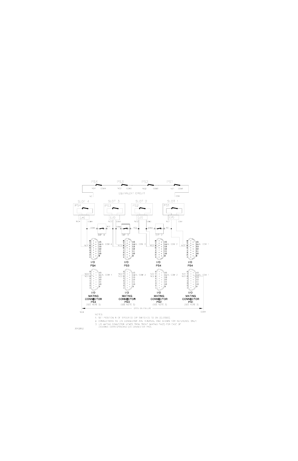
OPEN ON FAILURE USING REAR PANEL DIP SWITCHES
The open on failure alarm for multiple power supplies is accomplished by setting the associated
DIP switch, position 8, to ON (closed) for each slot included in the alarm circuit as indicated in
Figure 2-16. Setting DIP switch position 8 to ON (closed) connects the N.C. line to the COM line
of the adjacent power supply. Figure 2-16 illustrates an open on failure alarm configuration for
four power supplies where the alarm connections are made through the rear panel DIP switches
and the alarm signals are applied to the user’s alarm circuit via the I/O connector. Figure 2-17 is
the same, except alarm signals are available at the Alarm I/O Terminal Blocks.
CAUTION: The user is responsible for ensuring that the alarm circuit does not exceed
DIP switch specifications: 100mA, 50V d-c, maximum.
To configure PS1, PS2, PS3 and PS4 as open on failure, set position 8 of DIP switches DIP 2,
DIP 3, and DIP 4 to ON (closed). The failure indication (open circuit) will be present across
N.C.4 and COM 1.
FIGURE 2-16. TYPICAL OPEN ON FAILURE ALARM CONFIGURATION USING REAR PANEL DIP SWITCHES
WITH OUTPUT FROM I/O MATING CONNECTOR, SIMPLIFIED DIAGRAM