Table 1-1. compatible hsf power supplies, Table 1-2. ra 19-4c accessories (continued), Compatible hsf power supplies -4 – KEPCO RA 19-4C Operator Manual User Manual
Page 12: Ra 19-4c accessories -4
1-4
RA 19-4C 121013
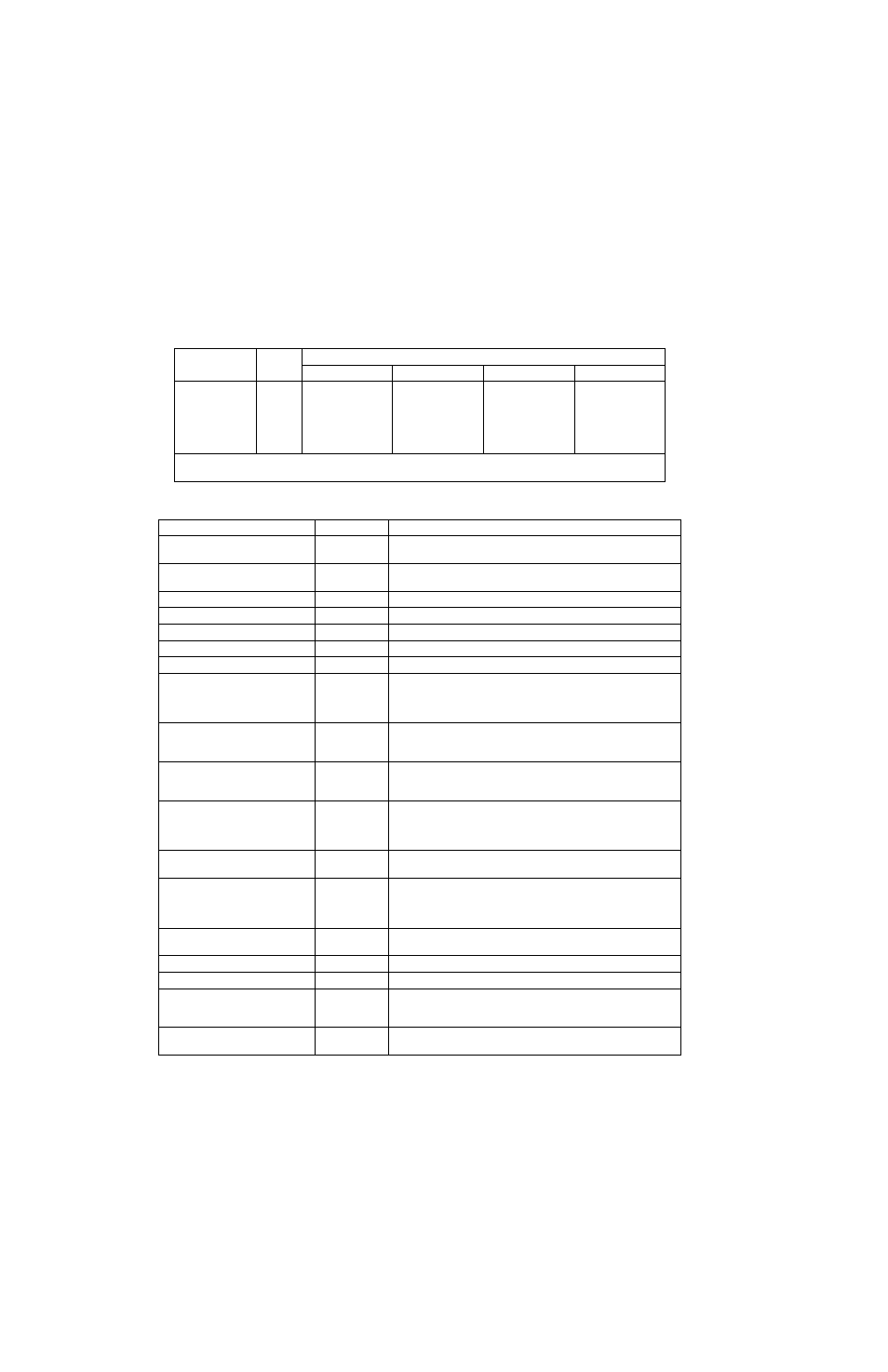
TABLE 1-1. COMPATIBLE HSF POWER SUPPLIES
MODEL
Total
Compatible HSF Models *
1200 Watts
1500 Watts
600 Watts
300 Watts
RA 19-4C
4 (max)
HSF 24-50
HSF 48-32
HSF 36-42
HSF 12-53
HSF 15-43
HSF 24-27
HSF 28-23
HSF 48-13
HSF 5-60
HSF 12-27
HSF 15-22
HSF 24-14
HSF 28-12
HSF 48-7
* Unless otherwise noted, Models that include a suffix specifying an option, e.g., M for Meter, C for Current Monitoring,
etc., are compatible. Contact Kepco Applications Engineering for assistance with non-standard configurations.
TABLE 1-2. RA 19-4C ACCESSORIES
ACCESSORY
PART NUMBER
USE
Screw, Thread forming
(4-40, 0.75 in. long, PHPH)
101-0480
Module Keying. eight (8) supplied with unit. Installed by user (see PAR.
2.3).
Line cord
118-1145
Connect to 30A, 125-250V a-c source power via NEMA 10-30P connec-
tion.
Line cord
118-1146
Connect to 32A, 250V a-c source power via IEC 309 connection.
Connector
142-0449
Mating Connector for I/O connector. Four (4) supplied with unit.
Filler Panel (1/4 Rack)
RFP 19-14C
Cover one unused 1/4 rack slot.
Filler Panel (1/2 Rack)
RFP 19-12C
Cover two unused 1/4 rack slots.
Bus bar, Series
172-0593
Connect Output Terminals, (–) to (+) for series operation.
Bus bar, Parallel, 2 Slots
(Clearance: 2.6mm)
172-0590
Connect slots 1 and 2, 2 and 3, or 3 and 4 in parallel; two bus bars
required for each paralleled slot: one for (+), one for (–). Bus bar is 3/32
in. thick, clearance between (+) and (–) is 2.6mm with two output studs.
Each stud is 5/16-18, 1.2-inch long minimum.
Bus bar, Parallel, 2 Slots,
1 Output Stud
(Clearance: 6.4mm)
172-0607
Same as P/N 172-0590 except bus bar is 1/8 in. thick and clearance
between (+) and (–) is 6.4mm; only one (1) output stud (5/16-18) per
busbar. Each stud is 5/16-18, 1.2-inch long minimum.
Bus bar, Parallel, 2 Slots
2 Output Studs
(Clearance: 6.4mm)
172-0615
Same as P/N 172-0590 except bus bar is 1/8 in. thick and clearance
between (+) and (–) is 6.4mm with two (2) output studs per busbar. Each
stud is 5/16-18, 1.2-inch long minimum.
Bus Bar, Parallel, 3 Slots
(Clearance: 4.5mm)
172-0591
Connect slots 1, 2 and 3, or 2, 3 and 4 in parallel; two bus bars required
for each paralleled set of slots: one for (+), one for (–). Bus bar is 1/8 in.
thick, clearance between (+) and (–) is 4.5mm with two (2) output studs
per busbar. Each stud is 5/16-18, 1.2-inch long minimum.
Bus Bar, Parallel, 3 Slots
(Clearance: 6.4mm)
172-0608
Same as P/N 172-0591 except clearance between (+) and (–) is 6.4mm.
Bus Bar, Parallel, 4 Slots
(Clearance: 4.5mm)
172-0592
Connect slots 1 through 4 in parallel; two bus bars required for each rack
adapter: one for (+), one for (–). Bus bar is 1/8 in. thick, clearance
between (+) and (–) is 4.5mm with three (3) output studs per busbar.
Each stud is 5/16-18, 1.2-inch long minimum.
Bus Bar, Parallel, 4 Slots
(Clearance: 6.4mm)
172-0609
Same as P/N 172-0592 except clearance between (+) and (–) is 6.4mm.
Bus Bar, Series
172-0593
Connects adjacent slots (+) to (–) to series configurations.
Hex Nut (5/16-18)
102-0105
Attach load cables to studs of optional bus bars.
Protective cover
137-0145
Clear plastic cover, protects against accidental contact with DC output
terminals. Four standoffs (not supplied), Kepco P/N 104-0385, required
for installation
Standoff (Protective cover)
104-0385
Four (4) required to install protective cover, Kepco P/N 137-0145.
Male/female, 8-32 x 1.5 in. long