2 n.c. alarm line (open on failure), N.c. alarm line (open on failure) -25, Alarm i/o terminal block, simplified diagram -25 – KEPCO RA 19-4C Operator Manual User Manual
Page 43: R. 2.5.2)
RA 19-4C 121013
2-25
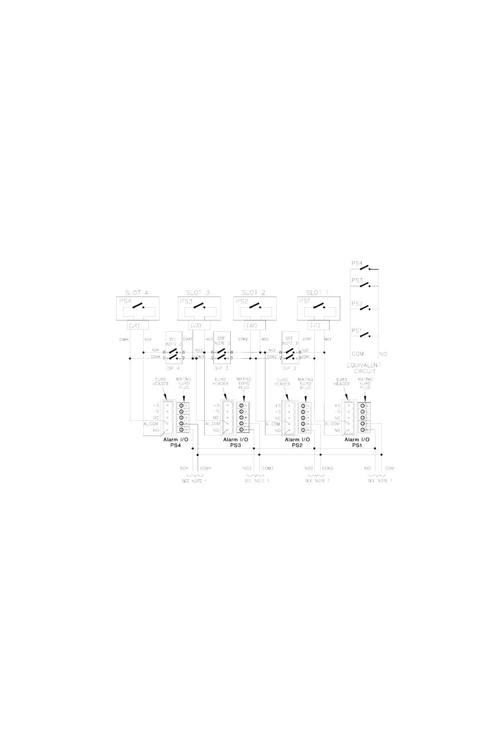
2.5.1.3
CLOSE ON FAILURE USING EXTERNAL WIRING AT ALARM I/O TERMINAL BLOCK
Close on failure for multiple power supplies can be accomplished by wiring N.O. and COM in
parallel at the Alarm I/O terminal block. DIP switches associated with slots included in the alarm
circuit must have positions 6 and 7 set to OFF (open). The failure indication (short circuit) will be
present across any pair of N.O. and COM lines. Figure 2-15 shows a close on failure alarm con-
figuration for four power supplies using external wiring at the Alarm I/O terminal blocks.
FIGURE 2-15. CLOSE ON FAILURE ALARM CONFIGURATION USING EXTERNAL WIRING AT
ALARM I/O TERMINAL BLOCK, SIMPLIFIED DIAGRAM
2.5.2
N.C. ALARM LINE (OPEN ON FAILURE)
The N.C and COM line of each HSF supply provide an open contact (open circuit) upon failure.
To configure multiple power supplies so that a failure of any supply produces a failure indication,
it is necessary to connect the N.C. line with the COM line of the next power supply, so the alarm
line is connected in series.