2 group control, Group control -11 – KEPCO RA 19-4C Operator Manual User Manual
Page 29
RA 19-4C 121013
2-11
2.4.2.2
GROUP CONTROL
Group control using one power supply designated as the master requires that the power supply
designated as the master be adjusted to the desired output voltage. All the other parallel-con-
nected units are slaves that track the output voltage of the master. This configuration can be
used to provide easy control of output bus voltage, however it is not truly redundant, since a fail-
ure of the master will cause a failure of the parallel-connected system. Failure of a slave
reduces the current capacity of the system, but it will continue to function.
For group control requiring a redundant system Kepco recommends configuring all parallel con-
nected units as slaves (see Table 2-3) controlled by a remote voltage. To eliminate a single point
failure possibility the remote voltage should have a backup and be connected in parallel to more
than one I/O connector.
At the rack adapter I/O connector use a shielded wire 6.6 feet (2M) maximum in length, for con-
nection of REF (pin 15), RV (pin 18), and –COM (pin 12) to the trimmer control or external volt-
age source (see Figure 2-7 or 2-8).
2.4.2.3
PARALLEL, MASTER SELECTED BY USER, SUPPLYING BALANCED CURRENT TO A
SINGLE LOAD
NOTE: For HSF 300W and 600W models, refer to associated power supply Operator Manual
for minimum load or output voltage limits needed to avoid “slave idle” or output oscilla-
tion (when slave is idle, output is off, no lights are lit, and alarm is set).
Figure 2-7 shows the connection of three power supplies in parallel to a single load. The output
voltage of all slave power supplies tracks the master. The master and slaves are determined by
the internal DIP switches, SW1 and SW2, of the HSF modules as defined in Table 2-3.
This configuration requires that CB (Current Balance) and RV (Remote Voltage) of all modules
be tied together, using either the DIP switches at the rear of the rack adapter, as shown in Figure
2-7, or by wiring the I/O mating connector as shown in Figure 2-8. Wiring of the I/O mating con-
nector allows non-adjacent slots to be connected in parallel.
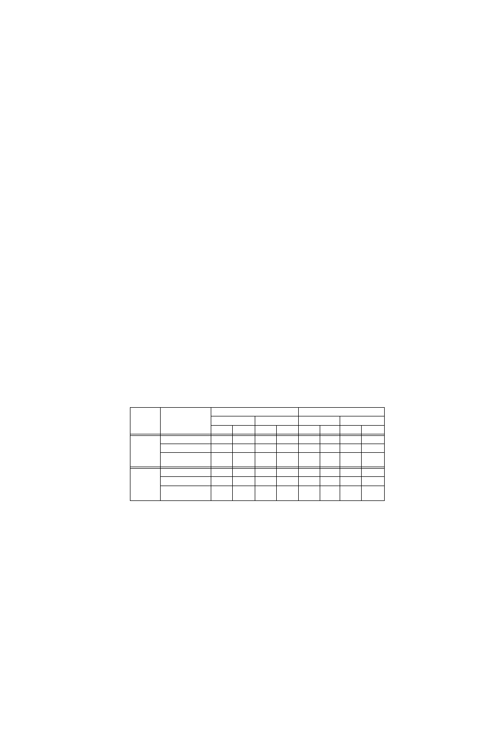
TABLE 2-3. HSF DIP SWITCH CONFIGURATION FOR GROUP CONTROL
(ALLOWS MASTER TO CONTROL OUTPUT WHILE SLAVES TRACK MASTER)
MASTER
OR
SLAVE
HSF DIP
SWITCH
POSITION
(See Note)
HSF 300W, 600W
HSF 1200W, 1500W
Vadj Control
External R or V
Vadj Control
External R or V
SW2
SW1
SW2
SW1
SW2
SW1
SW2
SW1
MASTER
Position 1 (REF)
OFF
ON
ON
OFF
OFF
ON
ON
OFF
Position 2 (RV)
ON
ON
ON
OFF
ON
ON
ON
OFF
Position 7 (COM)
OFF
See
Note (2)
OFF
See
Note (2)
ON
ON
ON
See
Note (2)
SLAVE
Position 1 (REF)
OFF
OFF
OFF
OFF
OFF
OFF
OFF
OFF
Position 2 (RV)
ON
OFF
ON
OFF
ON
OFF
ON
OFF
Position 7 (COM)
OFF
See
Note (2)
OFF
See
Note (2)
ON
OFF
ON
OFF
NOTES:
(1) HSF DIP Switches are located at the rear of each HSF module; refer to appropriate HSF manual for location.
(2) For HSF 600W, set SW1 position 7 to OFF
For HSF 300W, SW1 position 7 allows the DC ON indicator to powered by an internal auxiliary supply (see HSF
300W Operator Manual for details).