Precision Digital PD6730X User Manual
Page 20
PD6730X Vantageview Super Snooper Modbus Scanner
Instruction Manual
20
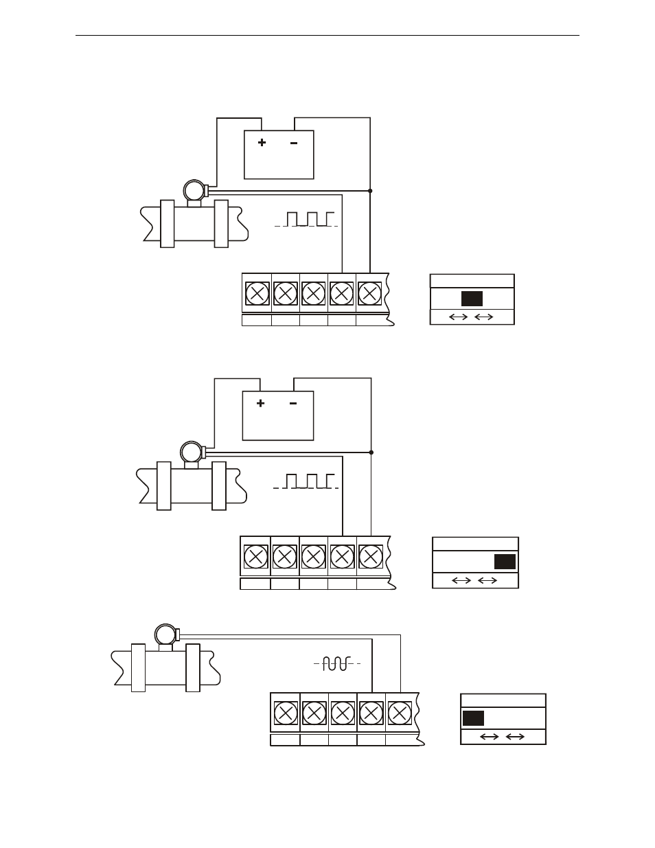
Pulse Input Signal Connections
Signal connections are made to a barrier terminal mounted in the base of the enclosure. Input level and
type are configured using the slide switches on the bottom of the display module as shown in the lower
right of the following figures.
Figure 8: Flowmeter Powered by External Supply (Active)
Figure 9: Isolated Flowmeter Powered by External Supply (ISO)
Figure 10: Self-Powered Magnetic Pickup Coil Flowmeter (Coil)
Flowmeter
(Pulse Output)
Power
Supply
COM RST
P+
S+
S-
INPUT LEVEL
mV V ISO
Flowmeter
(Pulse Output)
Power
Supply
COM RST
P+
S+
S-
INPUT LEVEL
mV V ISO
Flowmeter
(Magnetic Pickup Coil)
COM RST
P+
S+
S-
INPUT LEVEL
mV V ISO
This manual is related to the following products: