0 wiring diagrams – Magnum Energy Magnum Panel (MP Series) User Manual
Page 75
Page 68
© 2011 Magnum Energy, Inc.
4.0 Wiring Diagrams
4.0 Wiring Diagrams
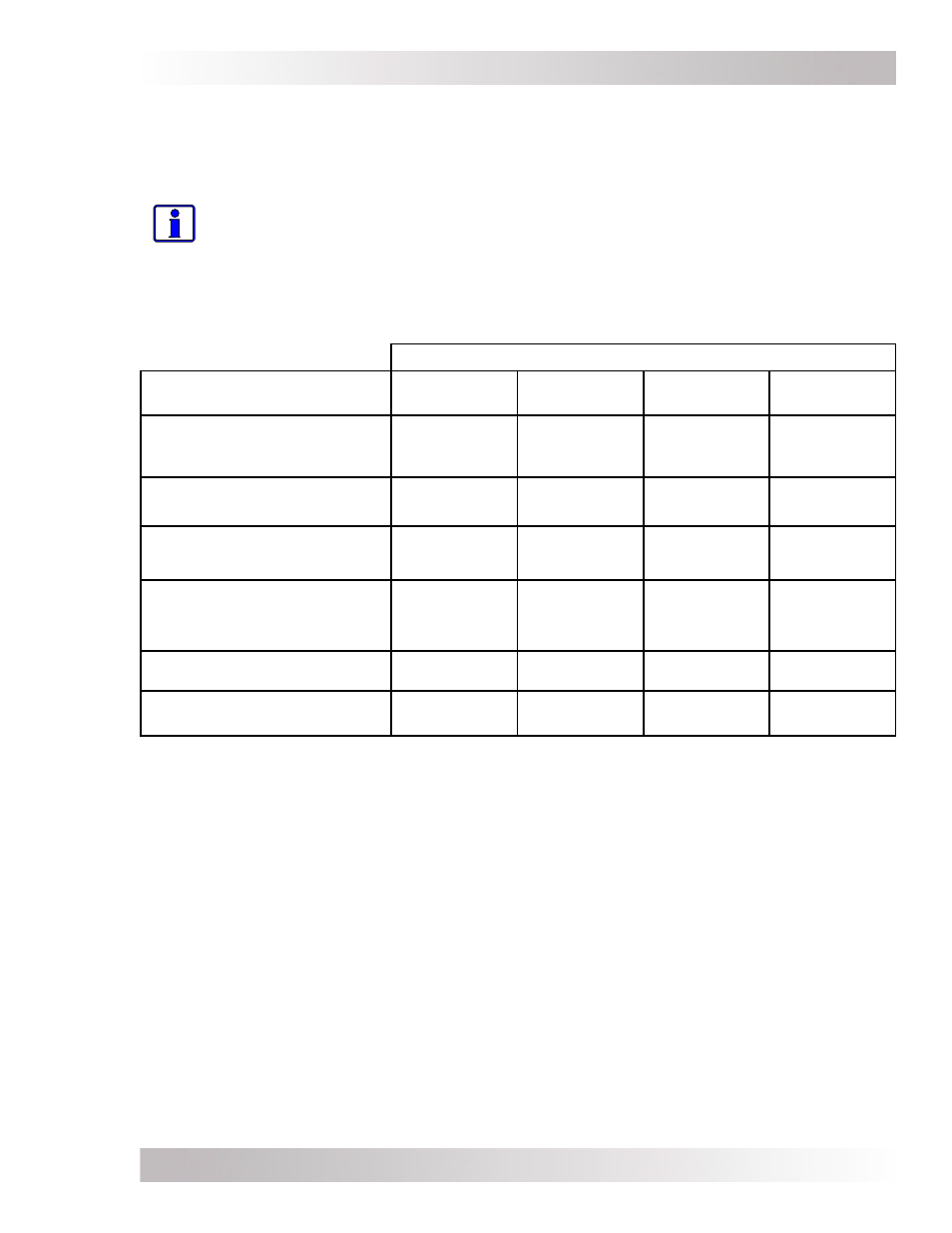
Diagrams of the AC, DC, and communications wiring for the different MP Series enclosures are
provided in this section to assist the system installer. Use Table 4-1 to quickly fi nd the wiring
diagram for your MP model.
Info: Due to the variety of applications and differences in local and national electrical
codes, these wiring diagrams should be used as a general guideline only. They are not
intended to override or restrict any national or local electrical codes; and, these diagrams
should not be the determining factor as to whether the installation is compliant, that
is the responsibility of the electrician and the onsite inspector.
Description of Wiring Diagrams:
• Inverter AC Input/Output Wiring - These diagrams show how to connect the inverter’s
AC input and output wires, separating them into two bundles (AC Input and AC Output), and
routing each bundle thru different strain-reliefs on the inverter.
• Inverter AC Wiring - These diagrams show the AC wiring inside the MP enclosure from the
inverter’s AC input and output wires.
• External AC Wiring - These diagrams show the AC wiring inside the MP enclosure to the
external AC source (i.e., generator or grid) and the external AC loads (main panel or sub-panel).
• DC Wiring (Inverter and External) - These diagrams show the DC wiring inside the MP
enclosure to the inverter’s DC terminals and the DC wiring to the external DC source (i.e.,
battery bank).
• Communications Wiring - These diagrams show the communications cables wired inside the
MP enclosure. These communications cables are for connecting the BTS and remote control
into and out of the MP enclosure.
• Full System Wiring - These diagrams show all the wiring (inverter AC/DC, external AC/
DC, and communications) as a fully complete system with the maximum amount of inverters
allowed for each specifi c model.
Table 4-1, MP Wiring Diagrams
MP Enclosure Models
Wiring Diagrams
MPSL-30D
MPSL-60S
MPSH-30D
MPDH-30D
Inverter AC Input/Output
Wiring
Figure 4-2
(MS-PAE
Series)
Figure 4-1
(MS4024)
Figure 4-2
(MS-PAE
Series)
Figure 4-2
(MS-PAE
Series)
Inverter AC Wiring
Figure 4-3a
Figure 4-4a
Figure 4-5a
Figure 4-6a
External AC Wiring
Figure 4-3b
Figure 4-4b
Figure 4-5b
Figure 4-6b
DC Wiring
(Inverter and External)
Figure 4-3c
Figure 4-4c
Figure 4-5c
Figure 4-6c
and
Figure 4-6d
Communications Wiring
Figure 4-3d
Figure 4-4d
Figure 4-5d
Figure 4-6e
Full System Wiring
Figure 4-3e
Figure 4-4e
Figure 4-5e
Figure 4-6f