Magnum Energy DC Breakers (BR-DC) User Manual
Magnum Energy Equipment
DC Load Breakers (Back Mount Type) Instruction Sheet
Part Number: 64-0041 Rev C
1
Magnum Energy, Inc.
2211 West Casino Rd.
Everett, WA 98204
www.magnumenergy.com
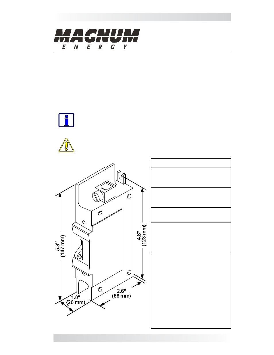
Figure 1, Physical Dimensions
Introduction
The BR-DC75-BM and BR-DC100-BM are DC circuit breakers that can be used
as disconnects for charge controllers and DC loads. The breaker is either a
75-amp (PN: BR-DC75-BM) or a 100-amp (PN: BR-DC100-BM). Both have a
slotted bracket that allows them to be easily mounted to a mounting plate inside
the MP (Magnum Panel) and MMP (Mini Magnum Panel) system enclosures.
These circuit breakers are magnetic-hydraulic, back-mountable, general
purpose E-Frame type with front accessible pressure terminal connectors that
accept #14 through #0 AWG copper or aluminum wire.
Specifi cations
Approvals
• UL 489 Listed
• CSA Certifi ed C22.2 No. 5
Interrupting Capacity
• 5,000 amperes at 125VDC
• 25,000 amperes at 65VDC
Trip Time Delay
• Delay 53 (DC long delay)
Recommended Torque:
• #14 to #18 AWG = 35 in. lbs.
• #8 AWG = 40 in. lbs.
• #6 to #4 AWG = 45 in. lbs.
• #3 to #0 AWG = 65 in. lbs.
Physical:
• Weight: ~9 oz. (255 grams)
• Dimensions: See Figure 1
• Terminals: front connected,
AL9CU dual-rated, pressure
terminals. Accepts #14 to #0
AWG copper or aluminum wire
(both 60° C and 75° C rated).
• Mounting: Attaches to back
mounting plate with #8-32 x 1/2”
(T20 head) Torx screws through
6/32 mounting inserts (torque to
6-8 in. lbs.).
Info: These breakers are not 100% continuous duty rated. To use
these breakers for continuous operation, they need to be derated
to 80%. For example, the BR-DC75-BM (75 amp) breaker can be
operated at 60 amps continuous (75 x .8 = 60 amp).
CAUTION: These breakers must be mounted in a vertical position
to meet the specifi ed trip current and trip delay curve.
Sizes shown in
inches (mm)