0 installation – Magnum Energy Magnum Panel (MP Series) User Manual
Page 46
© 2011 Magnum Energy, Inc.
Page 39
3.0 Installation
3.6.3
Inverter AC Wires and Overcurrent Protection
The inverter’s AC input and output wiring must be sized per the local electrical safety code
requirements to ensure the wires’ ability to safely handle the inverter’s maximum load current. AC
wiring is required to be protected from short circuits and overloads by an overcurrent protection
device, and have a means to disconnect the AC circuits.
The wires provided in the MP AC Wire Kit (as listed in Table 3-4 for your particular MP enclosure
model) are sized to handle the inverter’s maximum load current. The MP enclosure provides AC
circuit breakers for the inverter’s AC input. These breakers are branch circuit rated and can be
used as the overcurrent protection and the AC disconnect device as long as the wires in the MP
AC Wire Kit for you particular MP enclosure (or wires with at least the same rating) are used. If
you are using other wire/circuit breaker sizes, refer to the appropriate electrical codes for proper
sizing requirements.
When parallel stacking, a Magnum MS4024PAE or MS4448PAE inverter will be used. The full AC
continuous pass-thru capacity of these inverters is 30 amps for each AC leg (AC HOT 1 or AC HOT 2),
and requires a maximum 30 amp breaker on each AC input to protect the inverter’s internal pass-
thru relay. This correlates with the MPSL-30D, MPSH-30D, or MPDH-30D models, which include a
double-pole 30 amp input inverter breaker and requires a minimum wire size of #10 AWG
1
in conduit.
When series stacking, the Magnum MS4024 inverter will be used. The AC HOT 1 and AC HOT 2 in
this inverter may be combined to obtain a 60 amps pass-thru capability. When tying the AC HOT
1 and HOT 2 together for a 60 amp continuous pass-thru capability, the AC input to the inverter
requires a 60 amp breaker. This correlates with the MPSL-60S models, which include a single 60
amp breaker for each inverter and requires a minimum wire size of #6 AWG
1
in conduit.
Info: Additional space is provided in the MP enclosure to allow an AC breaker to be
installed for each additional inverter installed. These breakers are included with the
MPX Extension Kit along with the required hardware and wires for installation.
Note 1 - This wire must be copper with a minimum rating of 300V, 75°C at an ambient temperature of 30°C.
Note 2 - This wire is longer than required to allow at least 7” to be cut and used for connecting to the bottom
of the inverter AC input breakers.
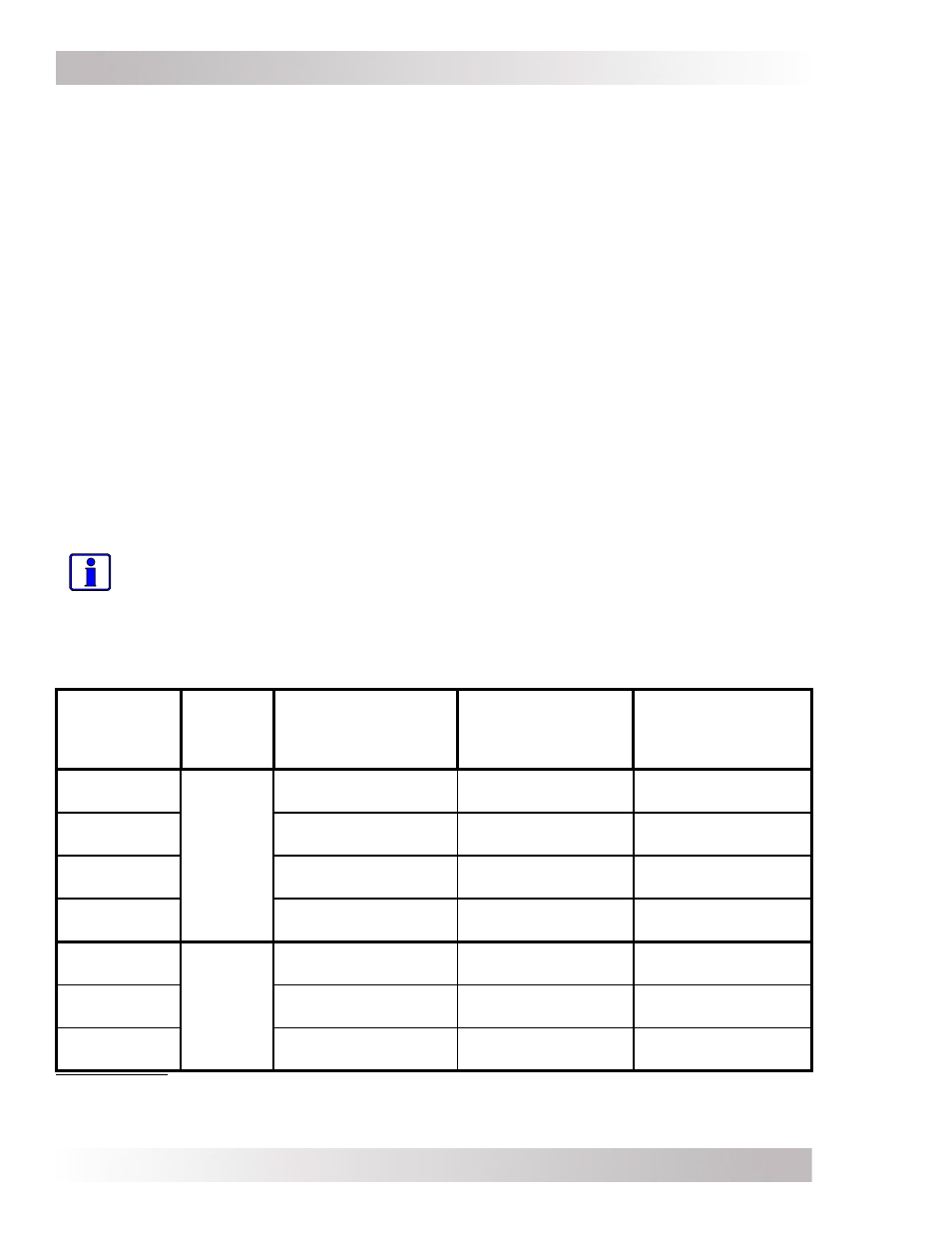
Table 3-4, MP AC Wire Kits
AC Wire
Reference
Separate
Wires
into:
A80-MPAC-30D-SH
(for MPSL-30D,
MPSH-30D and
MPDH-30D/AC Side)
A80-MPAC-60S-SH
(for MPSL-60S)
A80-MPAC-30D-LG
(for MPDH-30D/DC
Side)
INV HOT 1
IN
AC
INPUT
Side
(3 wire
bundle)
#10 AWG Black
(24")
2
#6 AWG Black
(24")
2
#10 AWG Black
(33")
2
INV HOT 2
IN
#10 AWG Red
(24")
2
NA (provided with
MPX wire kit)
#10 AWG Red
(33")
2
INV NEUTRAL
IN
NA (MS-PAE neutrals
in common)
#6 AWG White
(24")
NA (MS-PAE neutrals
in common)
INV AC
GROUND
#10 AWG Green
(24")
#10 AWG Green
(24")
#10 AWG Green
(33")
INV HOT 1
OUT
AC
OUTPUT
Side
(2-3 wire
bundle)
#10 AWG Black
w/Stripe (24”)
2
#6 AWG Black
w/Stripe (24”)
2
#10 AWG Black
w/Stripe (33”)
INV HOT 2
OUT
#10 AWG Red
w/Stripe (24”)
2
NA (provided with
MPX wire kit)
#10 AWG Red
w/Stripe (33”)
2
INV NEUTRAL
OUT
#10 AWG White
(24”)
#6 AWG White
w/Stripe (24”)
#10 AWG White
(33”)