0 installation, Ms4024 i, Ac transfer switch flux ca pacitor gener ator – Magnum Energy Magnum Panel (MP Series) User Manual
Page 28: Me-bmk-ns battery monitor (magnum accessory) dc, Enerator, Ower, Uput, Tility, Utput, Lectrical
© 2011 Magnum Energy, Inc.
Page 21
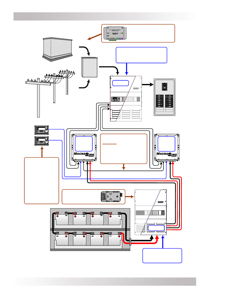
3.0 Installation
Figure 3-4, MP Series Simplifi ed Series-Stacked Installation Diagram
MS4024
I
NVERTER
ME-AGS-N
Auto Gen Start Controller
(Magnum Accessory)
O
N
O
F
F
O
N
O
F
F
O
N
O
F
F
O
N
O
F
F
O
N
O
F
F
O
N
O
F
F
ON
OFF
O
N
O
F
F
O
N
O
F
F
O
N
O
F
F
O
N
O
F
F
O
N
O
F
F
O
N
O
F
F
G
ENERATOR
P
OWER
(120/240VAC O
UPUT
)
U
TILITY
P
OWER
(120/240VAC O
UTPUT
)
AC
Transfer
Switch
Flux Ca
pacitor
Gener
ator
E
LECTRICAL
P
ANEL
*
(120/240VAC L
OADS
)
B
ATTERY
BANK
*
A
MAIN
PANEL
AND
SUB
-
PANEL
MAY
BE
REQUIRED
AC
SIDE
ME-BMK-NS
Battery Monitor
(Magnum Accessory)
DC
SIDE
MPSL-60S (AC Side)
Includes Inverter Bypass &
AC Input/Output Breakers
ME-ARC (x2)
Advanced Remotes
- for inverter set up
and monitoring
(Magnum
Accessory).
The ME-RTR may
be used if identical
settings are used
on both inverters.
Series Stacking Cable,
required to stack MS4024
inverters in series.
(Magnum Accessory).
Included with MPXS-60S
Extension.
MPSL-60S allows a maximum of two
MS4024's to be stacked in series
MPSL-60S (DC side)
Includes DC Shunt &
DC Disconnects
MS4024
I
NVERTER