0 installation – Magnum Energy Magnum Panel (MP Series) User Manual
Page 55
Page 48
© 2011 Magnum Energy, Inc.
3.0 Installation
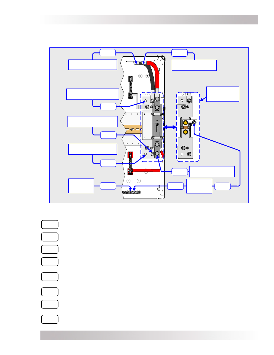
Figure 3-21, DC Wiring Connection Points for MPSL Models
DC8A
DC6
DC8B
DC1
DC2
DC4
DC7
DC5
DC3
3.7.5
DC Wiring Connection Points
Figures 3-21 thru 3-23 show the connection points for the DC wiring inside the MP enclosures.
DC N
EGATIVE
C
ABLE
C
ONNECTION
TO
I
NVERTER
A
DDITIONAL
I
NVERTER
DC N
EGATIVE
C
ABLE
C
ONNECTION
DC G
ROUNDING
E
LECTRODE
C
ONNECTIONS
A
DDITIONAL
B
ATTERY
B
ANK
N
EGATIVE
C
ABLE
C
ONNECTION
B
ATTERY
B
ANK
P
OSITIVE
C
ABLE
C
ONNECTION
DC P
OSITIVE
C
ABLE
C
ONNECTION
TO
I
NVERTER
DC E
QUIPMENT
G
ROUNDING
C
ONNECTION
B
ATTERY
B
ANK
N
EGATIVE
C
ABLE
C
ONNECTION
DC C
ONNECTIONS
(
UNDER
THE
DC
D
ISCONNECT
)
DC1
Inverter’s DC Negative Cable Connection - Cable connection to Magnum inverter’s
DC negative terminal. Electrically connected to the top of the DC shunt.
DC2
Inverter’s DC Positive Cable Connection - Cable connection to Magnum inverter’s
DC positive terminal. Electrically connected to the top of the inverter’s DC disconnect.
DC3
Additional Inverter DC Negative Cable Connection - Provided so that as more inverter’s
are added, cables can be added and connected to the inverter’s DC negative terminals.
DC4
Battery Bank Negative Cable Connection - DC Negative Busbar connection (bottom
connection of DC shunt); connects cables to the battery bank’s negative terminal.
DC5
Additional Battery Bank Negative Cable Connection - Provided to connect
additional cables to the battery bank’s negative terminal when additional Magnum
inverters are installed.
DC6
Battery Bank Positive Cable Connection - Bottom of the inverter’s DC disconnect
breaker; connects the battery cable to the battery bank’s positive terminal.
DC7
DC Equipment Grounding Connection - This busbar is used as the common DC
equipment ground point for all DC equipment connected in the MP/inverter system.
DC8
DC Grounding Electrode Connections - These are the connection points for the MP/
inverter system to the DC grounding electrode. Use DC8A for #6 to #1/0 AWG wires,
and DC8B for greater than #1/0 AWG wires.