Magnum Energy Magnum Panel (MP Series) User Manual
Page 41
Page 34
© 2011 Magnum Energy, Inc.
3.0 Installation
R
IGHT
S
IDE
V
IEW
BP-D
(D
UAL
M
OUNTING
B
ACKPLATE
)
MPDH-30D
(AC
AND
DC S
IDE
E
NCLOSURES
)
M
AGNUM
PAE S
ERIES
I
NVERTER
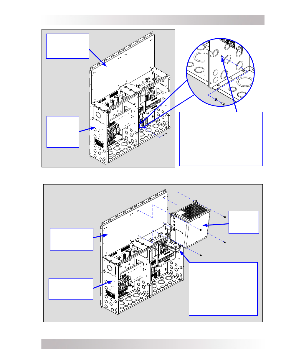
Figure 3-16d, Mounting First Inverter - MP Dual Enclosure
Figure 3-16c, Connecting the Two Sides Together - MP Dual Enclosure
BP-D
(D
UAL
M
OUNTING
B
ACKPLATE
)
MPDH-30D
(AC
AND
DC S
IDE
E
NCLOSURES
)
Note: Screw the two enclosures
together at this location to ensure
they are electrically at the same
potential. Use the #10-32 x 3/8”
screw (T25 Torx drive) and lock
washer that is attached to the
AC side of the MPDH-30D at the
opposite side of this location
(see Item 17, Figure 2-10a).
Note: Prior to mounting
the inverter, connect and
separate the AC input and
output wires within the
inverter, and then route
the wiring through the MP
enclosure. Ensure the AC
access plate is reattached
to the inverter.