Magnum Energy Magnum Panel (MP Series) User Manual
Page 34
© 2011 Magnum Energy, Inc.
Page 27
3.0 Installation
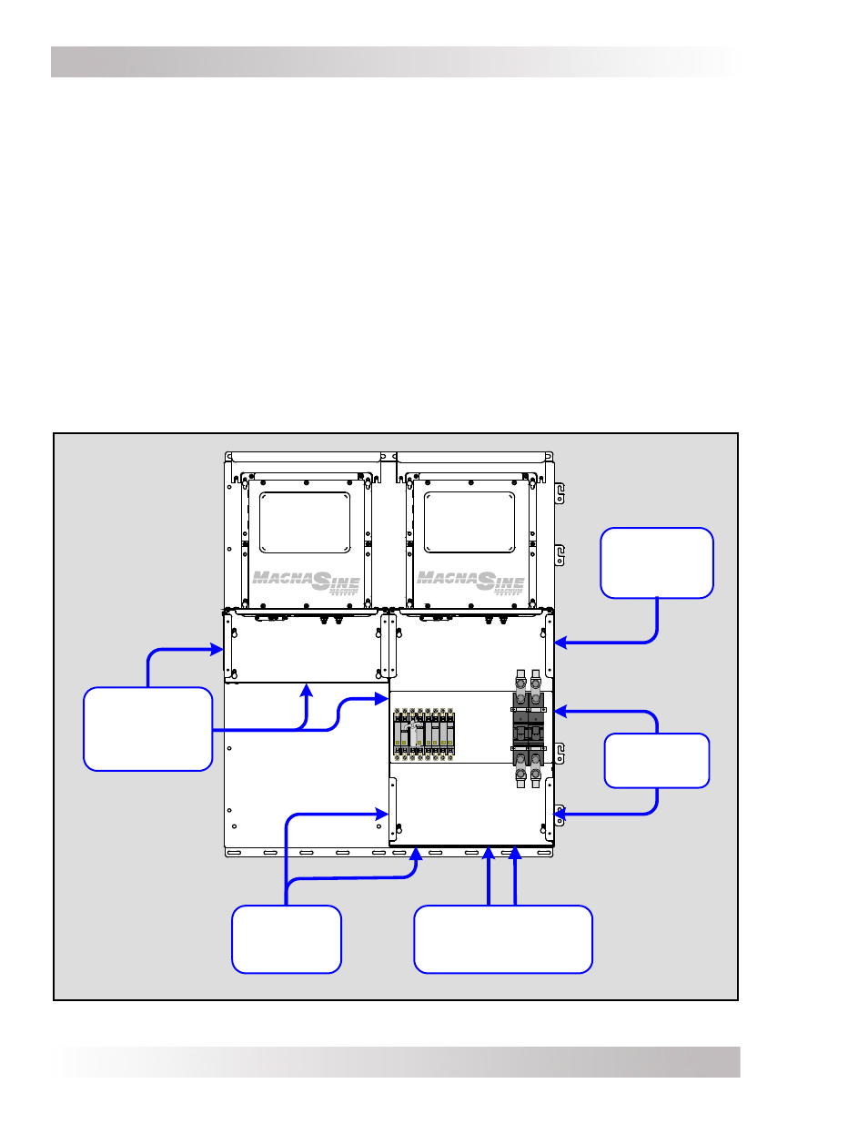
Figure 3-10, Conduit/Wire Routing
3.3.2
Planning Wire/Conduit Runs and Removing Knockouts
The MP enclosure is designed to provide ample room for wiring and comes standard with knockouts
to facilitate conduit installation for wire runs. See Figure 3-13 or 3-14 (depending on you model) to
see the size and location of these conduit knockouts. The 1/2”, 3/4”, and 1” knockouts are normally
used for the AC circuits, PV array, DC loads, and other smaller input cables. The 1 1/2” and 2”
knockouts are used to connect to the battery bank. Remove the appropriate knockout close to the
terminal where that wire connects, or whichever one works for the way your fi eld wiring comes in.
Before removing any knockout, review Figure 3-10 and think about all the wiring required and
where you are going to route the different circuits; such as:
• Wiring from the MP enclosure to the AC loads (AC sub-panel)
• Wire runs from the AC source (utility and/or a generator) to the MP enclosure
• Battery cable wiring from the battery bank to the MP enclosure
• Additional wiring from any external DC source (PV, wind, or hydro) to the MP enclosure
• Small signal wiring (remote controls, battery monitoring, auto gen starting)
• PV array and charge controller wiring
• Attaching lightning arrestors
MP
Enclosure
MPX
Enclosure
PV Array
and
DC Loads
Charge
Controllers
Battery Cables
and
DC/System Ground
AC Source
and
AC Loads
Remote/
Router
and
Accessories