0 installation – Magnum Energy MM-AE Series User Manual
Page 18
©
2010 Magnum Energy, Inc.
12
2.0 Installation
The DC wires must have soldered and crimped lugs, crimped copper
compression lugs, or aluminum mechanical lugs. Soldered connec-
tions alone are not acceptable for this application.
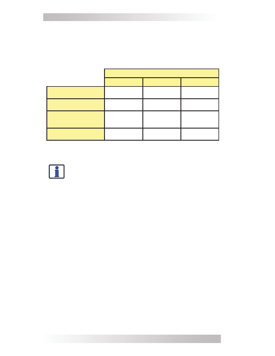
Table 1, Recommended DC Wire/Overcurrent Device
If the inverter is expected to operate at a distance greater than
three feet from the battery bank, the DC wire size will need to be
increased to overcome the increase in resistance – which affects the
performance of the inverter. Continue to use the overcurrent device
and DC ground wire previously determined from Table 1 and then,
refer to Table 2 to determine the minimum DC wire size you need for
various distances based on your inverter model.
Note 1 - Maximum Continuous Current is based on the inverter’s continuous
power rating at the lowest input voltage with an ineffi ciency factor.
Note 2 - Per the NEC, the DC grounding electrode conductor can be a #6
AWG conductor if that is the only connection to the grounding electrode and
that grounding electrode is a pipe, rod, or plate electrode.
Note 3 - Wire size is based on the requirements needed to increase effi cien-
cy and reduce stress to the inverter.
Note 4 - The next larger standard size overcurrent device may be used if
the de-rated cable ampacity falls between the standard overcurrent devices
found in the NEC.
Info: The term “in free air” is defi ned by the NEC as not
encased in conduit or raceway.
Inverter Model
MM612AE
MM1512AE
MM1524AE
Maximum Continuous
Current¹
80 amps
200 amps
100 amps
DC Grounding
Electrode Wire Size
# 6 AWG
# 6 AWG
# 6 AWG
Minimum DC Wire Size
(90˚C rating in free air)
# 2 AWG
(190 amps)
# 1/0 AWG
(260 amps)
# 1/0 AWG
(260 amps)
Maximum DC
Fuse Size
200 amps with
time delay
300 amps with
time delay
300 amps with
time delay