Magnum Energy MM-AE Series User Manual
Page 16
©
2010 Magnum Energy, Inc.
10
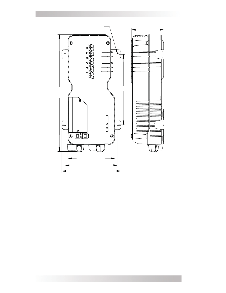
2.0 Installation
Figure 8, MM-AE Series Inverter/Charger Dimensions
M ounting holes x 4
[¼ ” (0.25 ") diam eter ]
10 .0"
~ 16
5/8
"
(16 .59 ")
~ 6
3/4
" (6.71")
~ 8
7 /16
" (8.41 ")
~ 7 ½ " (7.51")
~ 4
11 /16
"
(4.66 ")
Wiring Guidelines
• Before connecting any wires, determine all wire routes to and
from the inverter throughout the home or cabin.
• Conductors passing through walls or other structural members
must be protected to minimize insulation damage such as
chafi ng, which can be caused by vibration or constant rubbing.
• Always check for existing electrical, plumbing, or other areas
of potential damage prior to making cuts in structural surfaces or
walls.
• Make sure all wires have a smooth bend radius and do not be-
come
kinked.
• Both AC and DC overcurrent protection must be provided as part
of the installation.