Yaskawa VS-616G5 Series Revision F Programming Manual User Manual
Page 98
98
VS-616G5 Programming Manual
Section H: Control Circuit Terminals
H3 Analog Inputs
Selects the type of signal input at terminal 14.
The resolution of terminal 14 is 10 bit.
Note:
To enable terminal 14 for a voltage signal (settings: “0” or “1”), cut jumper wire J1 on the con-
trol printed circuit board. J1 is located on the bottom left-hand corner of the control board
directly behind terminal 13.
Selects the multi-function analog input function for terminal 14 (see Terminal 16 Multi-function Selec-
tion for details).
Setting Range:
0.0 to 1000.0%
Factory Default: 100.0%
Sets the terminal 14 input gain level when the reference current is 20mA. See Figure 46, on page 95.
Setting Range:
-100.0 to 100.0%
Factory Default: 0.0%
Sets the terminal 14 input bias level when the reference current is 4mA. See Figure 46, on page 95.
Setting Range:
0.00 to 2.00s
Factory Default: 0.00s
Sets up a delay filter time constant at terminals 13, 14 and 16. This filter inserts a delay between the
time the command is input to the time it is received by the inverter.
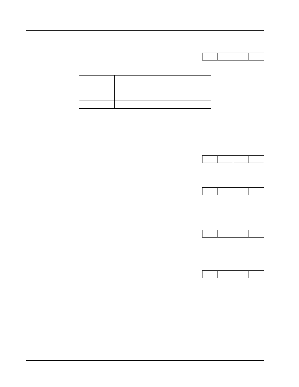
H3-08 Terminal 14 Signal Selection
Term 14 Signal
A
A
A
A
Setting
Description
0
0 to 10V input
1
-10 to +10V input
2
4 to 20mA (factory default)
H3-09 Terminal 14 Multi-function Selection
Terminal 14 Sel
A
A
A
A
H3-10 Terminal 14 Reference % Gain
Terminal 14 Gain
A
A
A
A
H3-11 Terminal 14 Reference ±% Bias
Terminal 14 Bias
A
A
A
A
H3-12 Analog Input Filter Time Constant
Filter Avg Time
A
A
A
A