Yaskawa VS-616G5 Series Revision F Programming Manual User Manual
Page 40
V/f
V/f w/PG Open Loop
Vector
Flux
Vector
40
VS-616G5 Programming Manual
Setting Range:
0.000 to 10.000s
Factory Default:
0.500s
The ASR integral time 2 is an additional integral time adjustment.
Sets ASR frequency compensation limit as a percentage of maximum output frequency (El -04). This
function is enabled when V/f control with PG feedback is selected as the control method (A1-02).
Setting Range:
0.000 to 0.500s
Factory Default:
0.004s
Mechanical backlash in an application causes secondary current (I
2
) reference variations in the motor’s
rotor. This condition can prevent the adjustment of ASR parameters.The output delay time constant is
used to control these secondary current (I
2
) reference variations.
Setting Range:
0.0 to 400.0Hz
Factory Default:
0.0Hz
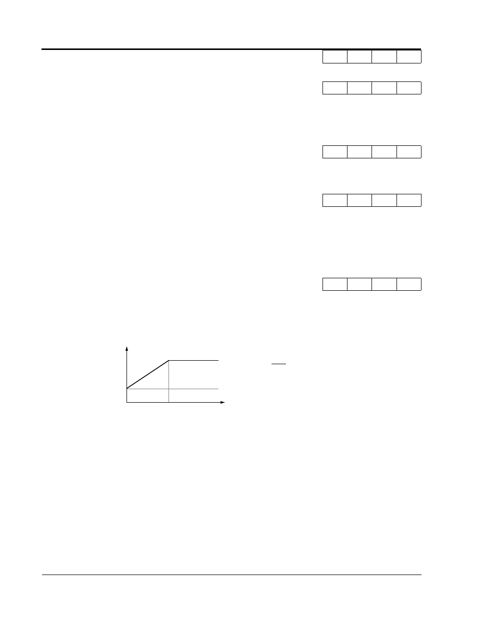
Sets frequency to change ASR proportional gain and integral time constant in units of 0.1Hz when flux
vector control is selected.
Notes:
1.When C5-07 =”0”, proportional gain 1 (C5-01) and integral time 1 (C5-02) are selected.
2.During V/f control with PG feedback (A1-02 = “1”), the frequency switching level becomes
the maximum output frequency (E1-04).
C5-04 ASR Integral Time 2
ASR I Time 2
-
B
-
B
C5-05 ASR Limit
ASR Limit
-
A
-
-
C5-06 ASR Output Primary Delay Time
ASR Delay Time
-
-
-
A
C5-07 ASR Switching Frequency Level
ASR Gain SW Freq
-
-
-
A
C5-07
f
FB
=
Figure 22 ASR Switching Frequency Level
P
ga
in
·
I t
im
e
C5-01
C5-02
C5-03
C5-04
0
P = Number of Motor Poles
N = Motor RPM
P · N
120
f
FB
Motor Speed
* When C5-07 =”0”, proportional gain 1 (C5-01)
where:
and integral time 1 (C5-02) are selected.
or
E1-04
Section C: Tuning Parameters
C5 ASR Tuning