Yaskawa VS-616G5 Series Revision F Programming Manual User Manual
Page 150
150
VS-616G5 Programming Manual
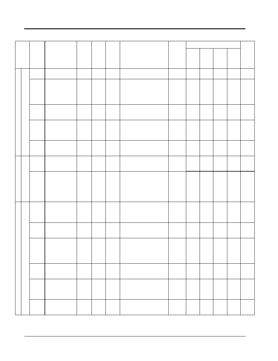
G
ro
up
H
T
er
m
in
al
F
un
ct
io
n
Fu
nc
tio
n
H
5
Se
ria
l C
om
S
et
up
M
O
D
BU
S
C
om
m
un
ic
at
io
n
H5-01
Station Address
(Serial Comm Adr)
0~20
1
1F
—
x
A
A
A
A
H5-02
Communication
Speed Selection
(Serial Baud Rate)
0~4
0
3
0 : (1200 Baud)
1 : (2400 Baud)
2 : (4800 Baud)
3 : (9600 Baud)
4 : (19200 Baud)
<1110>
x
A
A
A
A
H5-03
Communication
Parity Selection
(Serial Com Sel)
0, 1, 2
1
0
0 : (No Parity)
1 : (Even Parity)
2 : (Odd Parity)
x
A
A
A
A
H5-04
Stopping Method
After Communica-
tion Error
(Serial Fault Sel)
0~3
1
3
0: (Ramp to Stop)
1: (Coast to Stop)
2: (Fast - Stop)
3: (Alarm Only)
x
A
A
A
A
H5-05
Timeover Detection
(Serial Flt Dtct)
0, 1
1
1
0 : (Disabled)
1 : (Enabled)
x
A
A
A
A
Pr
ot
ec
tio
n
Fu
nc
tio
n
L1
M
ot
or
O
ve
rlo
ad
L1-01
Motor Protection
Selection
(MOL Fault Select )
0, 1
1
1
0: (Disabled)
1: (Coast to Stop)
x
B
B
B
B
L1-02
Motor Protection
Time Constant
(MOL Time Const)
0.1~5.0
min.
0.1 min.
1.0
When O2-09=1 [American
Spec] the setting range is
0.1~20min. The factory default
setting then becomes 8 min.
8 min. is the operation time
from a cold start.
x
B
B
B
B
Pr
ot
ec
tio
n
Fu
nc
tio
n
L2
P
ow
er
L
os
s
R
id
e
Th
ro
ug
h
L2-01
Momentary Power
Loss Detection
(PwrL Selection)
0, 1, 2
1
0
0 : (Disabled)
1 : Power loss ride through
(PwrL RideThru t)
2 : (CPU Power Active)
x
B
B
B
B
L2--02
Momentary Power
Loss Ride Through
(PwrL Ridethru t)
0.0~2.0
0.1s
0.7**
** Factory setting differs
depending on inverter capacity
(02-04).
x
B
B
B
B
L2-03
Min. Baseblock
Time
(PwrL Baseblock t)
0.1~5.0
0.1s
0.5*
* Factory setting differs
depending on inverter capacity.
Lower limit of setting range is
changed from 0 to 0.1.
<1110>
x
B
B
B
B
L2-04
Voltage Recovery
Time
(PwrL V/F Ramp t)
0.0~5.0
0.1s
0.3*
* Factory setting differs
depending on inverter capacity
(02-04).
x
A
A
A
A
L2-05
Undervoltage
Detection Level
(PUV Det Level)
150~
210
1V
190*
*Voltage Class
200V class=190V Det level
400V class=190V x 2= 380V level
575V class=190x575/200=546 level
x
A
A
A
A
L2-06
KEB Deceleration
Rate
(KEB Frequency)
0.0~
100.0
0.1%
0.0
—
x
A
A
A
A
Function
Parameter
No.
Name
(Digital Operator
Display)
Setting
Range
Setting
Unit
Factory
Setting
Remarks
(Digital Operator Display)
Change
during
Operation
o: Enabled
x: Disabled
Parameter Access Level
User
Setting
V/f
V/f
w/
PG
Open
Loop
Vector
Flux
Vector
Appendix
VS-616G5 Parameter List H Terminals